OSS21C function module
General data | |
|---|---|
Part number | 25780980 |
Current consumption from backplane bus | 100 mA |
Power loss | 2 W |
Certification according to UL | No |
Certification according to KC | No |
Housing material | PPE/PPE GF10 |
Mounting | Profile rail 35 mm |
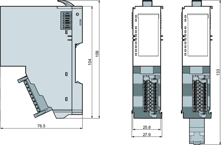
Dimensions (W × H × D) | 25.8 × 109 × 76.5 mm |
Net weight | 70 g |
Weight including accessories | 80 g |
Gross weight | 95 g |
Operating temperature | 0 °C to +60 °C |
Storage temperature | -25 °C to +70 °C |
Digital inputs | |
|---|---|
Number of counters | 3 |
Shielded cable length | 100 m |
Unshielded cable length | 1 m |
Nominal load voltage | DC 20.4 – 28.8 V |
Current consumption from load voltage L+ (without load) | 20 mA |
Nominal value | DC 20.4 – 28.8 V |
Input voltage for signal "0" | DC 0 – 5 V |
Input voltage for signal "1" | DC 11 – 28.8 V |
Input current for signal "1" | 3 mA |
2-wire BERO cable possible | Yes |
Maximum permitted BERO no-load current | 1.5 mA |
Input filter delay | 1 ms internal cycle, no filter |
Input characteristic | IEC 61131-2, type 3 |
Input data size | 3-bit |
Digital outputs | |
|---|---|
Number of counters | 1 |
Shielded cable length | 100 m |
Unshielded cable length | 1 m |
Nominal load voltage | DC 20.4 – 28.8 V |
Polarity reversal protection of the nominal load voltage | Yes |
Current consumption from load voltage L+ (without load) | 20 mA |
Output voltage "1" signal at minimum current | L+ (-0 V) |
Output voltage "1" signal at maximum current | L+ (-250 mV) |
Output current at "1" signal, nominal value | 500 mA |
Output current at "0" signal (residual current) max. | 5 μA |
Output delay from "0" to "1" | 1 ms internal cycle |
Output delay from "1" to "0" | 1 ms internal cycle |
Lamp load | 10 W |
Parallel connection of outputs for redundant control | Not possible |
Parallel connection of outputs for increased power | Not possible |
Control of a digital input | Yes |
Switching frequency for ohmic load | Maximum 300 Hz |
Switching frequency for inductive load | Maximum 0.5 Hz |
Switching frequency for lamp load | Maximum 10 Hz |
Limit (internal) for the inductive interrupting voltage | L+ (-45 V) |
Short-circuit protection of the output | Yes, electronic |
Response threshold of the protection device | 2.3 A |
Status, alarms, diagnostics | |
|---|---|
Status display | Green LED per channel |
Alarms | Yes, parameterizable |
Process alarm | No |
Diagnostic alarm | Yes, parameterizable |
Diagnostic function | Yes |
Diagnostic information can be read out | Possible |
Supply voltage display | Green LED |
Fault display for group fault | Red LED |
Data sizes | |
|---|---|
Input bytes | 36 |
Output bytes | 36 |
Parameter bytes | 56 |
Diagnostic bytes | 20 |
Electrical isolation | |
|---|---|
Between channels and backplane bus | Yes |
Between the areas | Backplane bus, 24 V DI/DO/encoder, motor output stage, FE (shield) |
Max. potential difference between inputs and Minternal (Vins) | DC 75 V/AC 50 V |
Insulation checked with | AC 500 V |
Positioning module | |
|---|---|
Number of channels | 1 |
Cable length (encoder) | 20 m shielded |
Input voltage (nominal value) | DC 48 V |
Input voltage (permitted range) | DC 20.4 – 57.6 V |
Motor current | 5 A |
Derating | Yes |
Max. motor cable length | 20 m shielded |
Output stage | 2 × full bridge PWM |
Short-circuit protection | Yes |
Brake chopper | External, if required |
PWM frequency | 32 kHz |
Microsteps | 64 |
Steps per revolution | Parameterizable |
Encoder type | A/B/Z track 5 V differential |
Max. encoder cable length | 20 m shielded |
Encoder frequency | 50 kHz |
Encoder resolution (internal) | Parameterizable |
Control type | Open loop, closed loop |
Controller temperature sensor | Yes |
H-bridge temperature sensor | Yes |
Positioning functions operating modes | |
|---|---|
Referencing to reference switch | Yes |
Positioning without encoder | Yes |
Positioning with encoder | Yes |
Speed control | Yes |
Torque control | Yes |
Terminal assignment
| No. | Name | Function |
|---|---|---|---|
| 1 | PA1 | Motor winding A – connection 1 |
2 | PA2 | Motor winding A – connection 2 | |
3 | 48 V | Motor voltage supply DC 20.4 V – 57.6 V | |
4 | ENC5V | Encoder voltage supply 5 V | |
5 | ENC+A | Encoder input +A (5 V/TTL) | |
6 | ENC+B | Encoder input +B (5 V/TTL) | |
7 | ENC+Z | Encoder input +Z (5 V/TTL) | |
8 | DI1 | Digital input 1 | |
9 | DO | Digital output | |
10 | PB1 | Motor winding B – connection 1 | |
11 | PB2 | Motor winding B – connection 2 | |
12 | M0V | Motor voltage supply GND | |
13 | ENCoV | Encoder voltage supply GND | |
14 | ENC-A | Encoder input -A (5 V/TTL) | |
15 | ENC-B | Encoder input -B (5 V/TTL) | |
16 | ENC-Z | Encoder input -Z (5 V/TTL) | |
17 | DI2 | Digital input 2 | |
18 | DI3 | Digital input 3 |

Dimension drawing
|