Terminal assignment of the MOVI-C® FIELD CONTROLLER
Attach units without a plug connector to the terminals as follows:
- De-energize the device. Pay attention to the 5 safety rules in chapter "Carrying out electrical work safely". Afterwards, wait 5 minutes.
- Let the device cool sufficiently before touching it.
- Undo the screws of the electronics cover. Remove the electronics cover.
- Route the cables through the cable glands into the connection box.
- Connect the device according to the following terminal assignment.
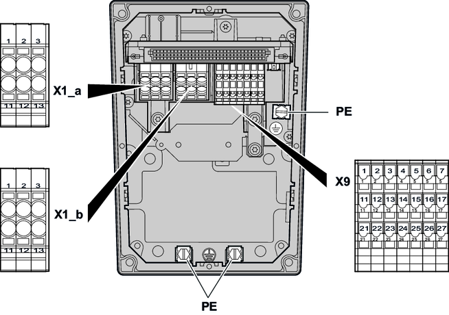
The following figure shows the terminal assignment in the connection box of the device:
The following table shows the terminal assignment of the device:
Terminal | No. | Marking | Function | |
|---|---|---|---|---|
X1_a | 1 | Brown | L1 | Line connection, phase L1 – IN |
2 | Black | L2 | Line connection, phase L2 – IN | |
3 | Gray | L3 | Line connection, phase L3 – IN | |
11 | Brown | L1 | Line connection, phase L1 – OUT | |
12 | Black | L2 | Line connection, phase L2 – OUT | |
13 | Gray | L3 | Line connection, phase L3 – OUT | |
X1_b | 1 | Brown | L1 | Line connection of drive units, |
2 | Black | L2 | Line connection of drive units, | |
3 | Gray | L3 | Line connection of drive units, | |
11 | Brown | L1 | Line connection of drive units, | |
12 | Black | L2 | Line connection of drive units, | |
13 | Gray | L3 | Line connection of drive units, | |
| – | – | PE | Protective earth connection |
X9 | 1 | – | +24 V | DC 24 V voltage |
2 | – | +24 V | DC 24 V voltage | |
3 | – | +24 V | DC 24 V voltage | |
4 | – | +24 V | DC 24 V voltage | |
5 | – | +24 V | DC 24 V voltage | |
6 | – | CAN_H | CAN data cable (high), | |
7 | – | RS+ | RS485 data cable (+), | |
11 | – | 0V24 | 0V24 reference potential | |
12 | – | 0V24 | 0V24 reference potential | |
13 | – | 0V24 | 0V24 reference potential | |
14 | – | 0V24 | 0V24 reference potential | |
15 | – | 0V24 | 0V24 reference potential | |
16 | – | CAN_L | CAN data cable (low), | |
17 | – | RS- | RS485 data cable (-), | |
21 | – | 24V_IN | DC 24 V voltage (IN) | |
22 | – | 0V24_IN | 0V24 reference potential (IN) | |
23 | – | res. | Reserved for internal connectionOnly for internal wiring. The signal is not approved for connection or use at the customer site! | |
24 | – | 24V_SW | Reserved for internal connection1) | |
25 | – | DI_SW | Reserved for internal connection1) | |
26 | – | CAN_GND | Reference potential for CAN data cable, | |
27 | – | RS_GND | Reference potential for RS485 data cable, | |

