Encoders
Observe the following notes before installation:
- SEW‑EURODRIVE offers prefabricated cables for connecting encoders. SEW‑EURODRIVE recommends using these prefabricated cables.
- When fabricating your own cables, make sure that the following requirements are met:
- Cross section of voltage supply cable:
- – At least 0.25 mm2 for cable lengths up to 50 m
- – At least 0.5 mm2 for cable lengths from 50 m up to 100 m
- Cross section of the signal wire:
- – At least 0.25 mm2
- Capacitance per unit length:
- – Maximum 70 pF/m – core/core
- – Maximum 120 pF/m – core/shield
- The cable must be shielded.
- Differential signals must be routed via twisted wires e.g. Data+ and Data-. Use shielded cables with twisted pair cores.
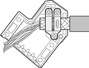
- Connect the shield over a wide area at both ends:
- At the encoder in the cable gland or in the encoder plug
- At the inverter in the housing of the D-sub plug

- Route the encoder cable separately from the power cables.
- To ensure a flawless shield connection, you must use an EMC screw fitting for the cable entry of the signal cable.
- For drives with plug-in connection, connect the shield in the encoder connector.
- The maximum cable length might be reduced depending on the technical data of the respective encoder. Observe the specifications of the encoder manufacturer. For information on the maximum cable lengths, refer to the product manual > chapter "CES11A multi-encoder card" > Technical data.
