Integrating and configuring the controller in the fieldbus network
Proceed as follows:
- You have already downloaded the device description file () of the controller from the SEW‑EURODRIVE homepage → www.sew-eurodrive.com and saved it locally on the engineering PC.
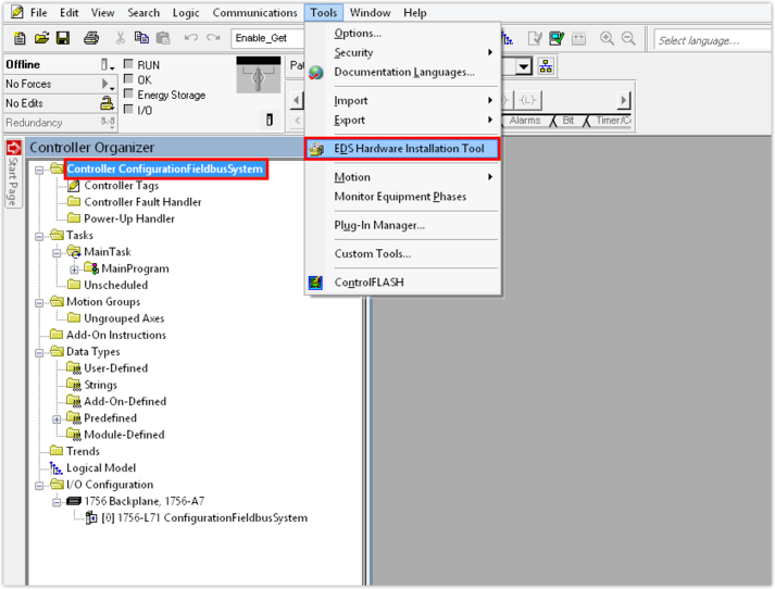
- Start the "Studio 5000 Logix Designer" tool and create a new Logix Designer project.
- Add an EtherNet/IP™ scanner to the project. Assign a name and enter the IP address of the EtherNet/IP™ scanner.
- Load the device description file to the Logix Designer.
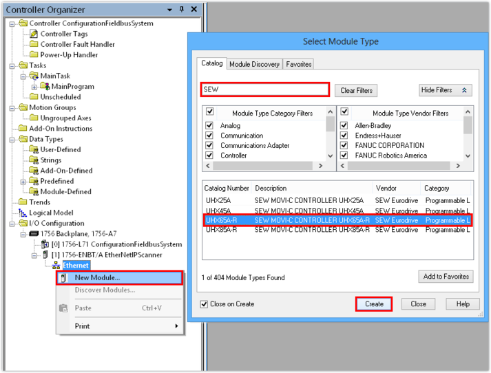
- Right-click to open the Ethernet interface context menu and add the communication partner.
- A module catalog is displayed.
- Select the controller. Set a filter to reduce the number of modules shown.
- In this example, "SEW" is filtered and the UHX65A-R controller is used as the communication partner.
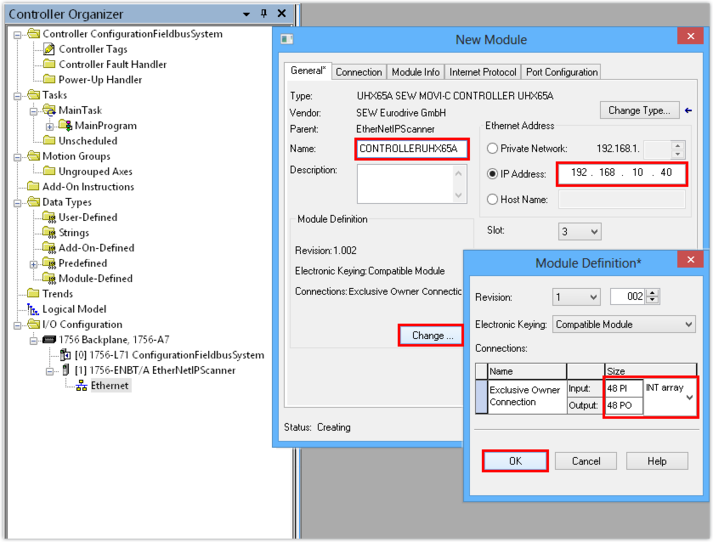
- Assign a project name for the controller.
- Enter the IP address of the controller. The PLC will address the device using this IP address.
- Select the number of process data words that you wish to use for communicating with the subordinated slaves. Set the data format for the process data words. The process data always contains 16 bits (data format INT).
- In this example, the IP address of the controller is 192.168.10.40. Each application inverter module (slave of the controller) is provided with 16 process data words for communication. This makes a total of 48 (3 × 16) process data words.
- If the direct integration of the device description file is not supported, set the following connection parameters:
Assembly instance | Value |
|---|---|
PO Data Exclusive Owner | 161 |
PI Data Exclusive Owner | 171 |
Listen Only | 192 |
Input Only | 193 |
- Save the Logix Designer project.
