Programming in the IEC program
- Exit the configuration menu and open the IEC project in the IEC Editor.
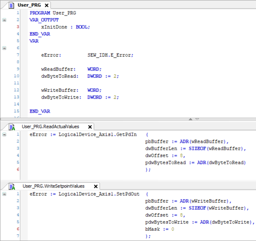
- In the IEC project in action User_PRG.ReadActualValues, transfer process data word 5 (byte offset = 8; see screenshot) using the method GetPdIn of the logic device assigned to the axis.
- The lower 6 bits in the wReadBuffer variable in the User_PRG program represent the state of the digital inputs.
- In the IEC project in action User_PRG.WriteSetpointValues, transfer process data word 5 using the method SetPdOut of the logic device assigned to the axis to the value defined in the wWriteBuffer variable.
- The lower 4 bits in the wWriteBuffer variable in the User_PRG program represent the state of the digital outputs.

