Processing jerk time
For processing a jerk time, the jerk time must be mapped to one of the free process data words in the inverter. Proceed as follows:
- The process data profile was extended to include additional process data words. For instructions, refer to the chapter Extending the process data profile.
- In MOVISUITE®, click the software module.
- The configuration menus of the software module are displayed.
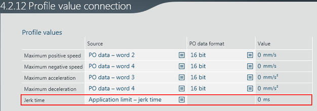
- Under "Functions" in the main menu, open the "Setpoints" menu and its submenu "Profile value connection".
- Select the required additional process data word for the "Jerk time".
- Exit the configuration menu and open the IEC project in the IEC Editor.
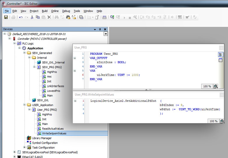
- In the IEC project, transfer the jerk time to the set process data word using the method SetAdditionalPdOut of the logic device assigned to the axis. To do so, first declare a variable uiJerkTime in the User_PRG (PRG) program and then set the required jerk time in this variable.
- Write the variable to the required process data word using the action User_PRG.WriteSetpointValues.


Trace recording
The following trace recording shows an example of the position and speed profiles as described in chapter Controlling the "Position control" operating mode with a jerk time of 1000 ms:

[1] | Velocity.In.xActivate |
[2] | Velocity.In.xStart |
[3] | Velocity.In.lrPosition |
[4] | Velocity.In.lrVelocity |
[5] | Velocity.Out.xInPosition |
Note:
The speed profile is no longer trapezoidal. The edges are rounded, which means the acceleration does not "jump" to the set value but gradually reaches the set value via the jerk time. Positioning takes accordingly longer. In this case, it takes twice the jerk time.
