Electronics connection
The functions assigned to the terminals and connectors depend on the device configuration:
- Without MOVIKIT® or parameters ex works (binary control), see chapter Configuration for terminal mode.
- MOVIKIT® Velocity Drive, see chapter Configuration for MOVIKIT® Velocity Drive.
- Parameters ex works, see chapter Configuration for parameters ex works.
The following table shows the availability of terminals depending on the device variant. The X6 spring-loaded terminals on the device and X5 on the gateway are pluggable.
Terminal | Design | Description | Availability by |
|---|---|---|---|
X5 | Cage clamp terminal | Input | CFX11A..Gateway |
X6 | Cage clamp terminal | STO terminal | ../CSO/.. |
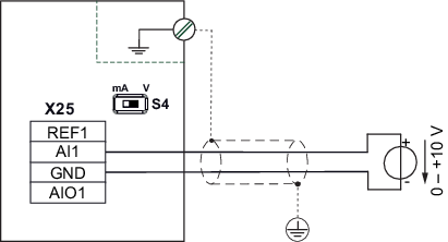
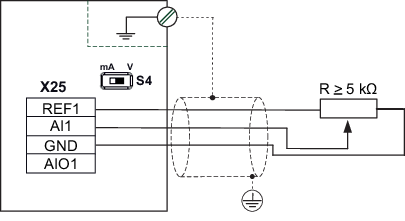
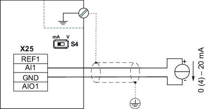
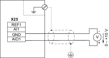
X25 | Cage clamp terminal | Signal terminals | All variants |
X26 | Cage clamp terminal | Signal terminals | All variants |
IN X30/X40 | RJ45 | System bus or fieldbus connection | CFX11A..Gateway |
OUT X30/X41 | RJ45 |
Signal terminal overview / connection diagram
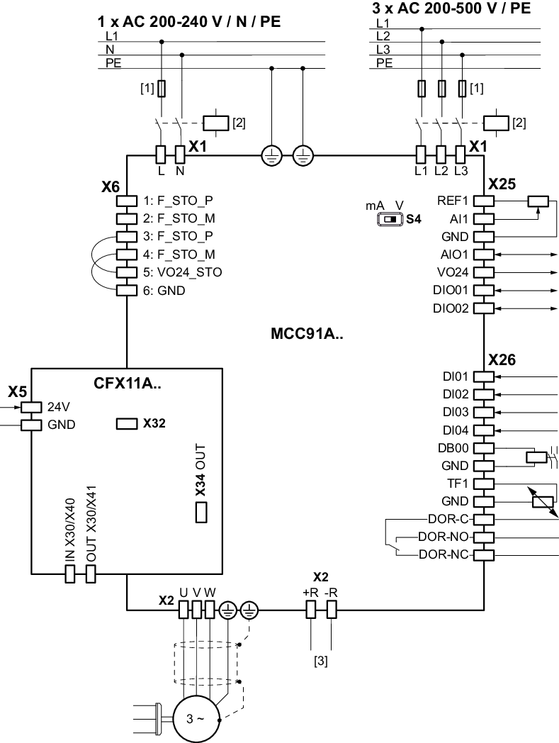

[1] | Line fuse |
[2] | Line contactor |
[3] | Braking resistor connection, see chapter Protecting braking resistors against thermal overload |
Additional information