Connecting the MDP92A‑0100 power supply module to the energy storage system
- Make sure that the requirements from chapter Discharging energy storage units before service work are implemented.
- Make the PE connection with a cable cross section of at least 16 mm2 directly at the PE ground busbar.
- Connect terminal X4: +UZ of the MDP92A-0100 device to an appropriate single-core cable with double insulation, e.g. single 600-O VDE V0/V 600/1000 V with a cable cross section of 35 mm2 with the DC choke L1 terminal 1. To do so, use the connection set with part number 28261666, which is used for two-row setup. Attach a ferrite sleeve. The ferrite sleeve must be ordered separately (part number 25665308). The ferrite sleeve enclosed to the devices is not suitable for this purpose. In the same way, connect terminal X4: -UZ of the MDP92A-0100 device to an appropriate single-core cable with double insulation, e.g. single 600-O VDE V0/V 600/1000 V with a cable cross section of 35 mm2 with the DC choke L1 terminal 2.
- Lay an appropriate single-core cable with double insulation with a cross section of 1.5 mm2 to 6.0 mm2 between the X12:6 (-ES) connection on the MDP92A‑0100 and terminal X1:1 (ES-) of the energy storage system.
- Lay a control cable for DC 24 V supply to connection X1:2 (DC 24 V) and X1:3 (DC 0 V). Match the cross section of this cable to the fusing.
- Connect the last existing station to the "IN" input of the BK1 bus coupler. Use the 5-meter cable with the part number 18179983, or alternatively the 10-meter cable with the part number 18179991.
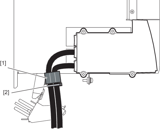
[1] | Ferrite sleeve |
[2] | Cable tie for securing the ferrite sleeve to the sheet metal |
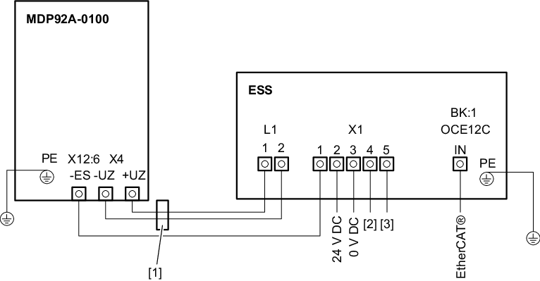
[1] | Ferrite sleeve |
[2] | Door position switch X1:4 |
[3] | Door position switch X1:5 |
