Operating modes
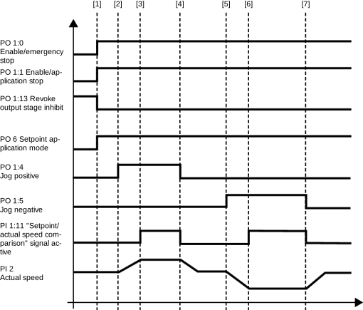
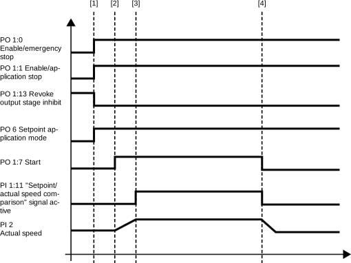
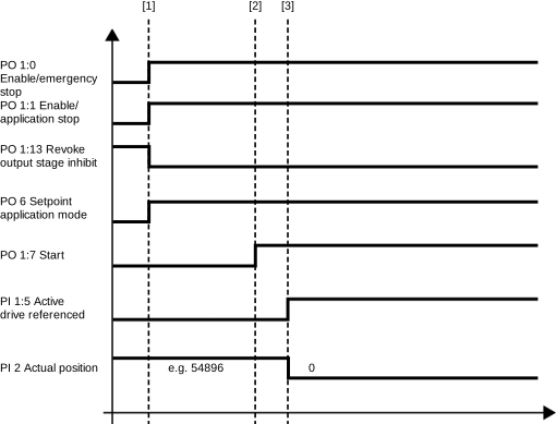
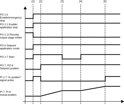
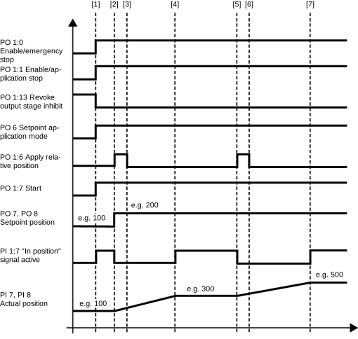
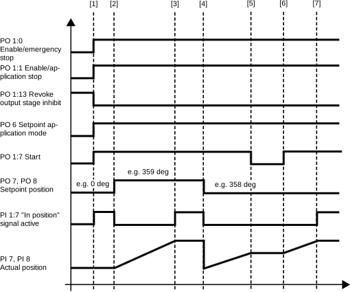
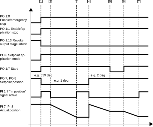
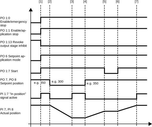
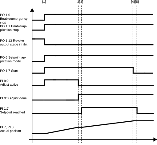
The following table shows the operating modes available in the operation of the software module. The operating mode is defined via a process data word of the software module. The drive is stopped when switching to another operating mode. Switching on the fly is not possible. The following chapters provide a cycle diagram for each operating mode to help you better understand the operating principle as well as the process sequence with a description of the signal states.
Note that the modulo operating modes can only be used if a cycle limit is set in the Limit values configuration menu.
For operating function block FCB 12, the configuration settings made in the MOVISUITE® configuration apply.
Operating mode | dec | Description |
|---|---|---|
Default | 0 | Causes to stop with the deceleration transferred via fieldbus. The drive is then switched to DefaultStop (FCB 02) and the brake is applied. |
Jog | 100 | Jog – position-controlled (FCB 10) |
101 | Jog – speed-controlled (FCB 10) | |
Speed | 200 | Speed (FCB 10) |
Referencing | INFORMATION: When using real axes, reference travel is performed on the inverter in FCB 12, for virtual axes on the MOVI-C® CONTROLLER. The set configuration applies to the operation of FCB 12. INFORMATION: If a variable reference offset for virtual axes has been specified once via operating mode 301, the last value transferred is also adopted as the reference offset in operating mode 300 until the next restart of the MOVI-C® CONTROLLER. Therefore, use either operating mode 300 or 301. | |
300 | Referencing – offset configured | |
301 | Referencing – offset fieldbus | |
Positioning | 400 | Positioning – absolute (FCB 10) |
401 | Positioning – relative (FCB 10) | |
402 | Positioning – modulo positive (FCB 10) | |
403 | Positioning – modulo negative (FCB 10) | |
404 | Positioning – modulo short (FCB 10) | |
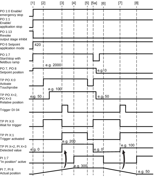
420 | Positioning absolute – Touchprobe remaining distance in direction of travel (FCB 10) | |
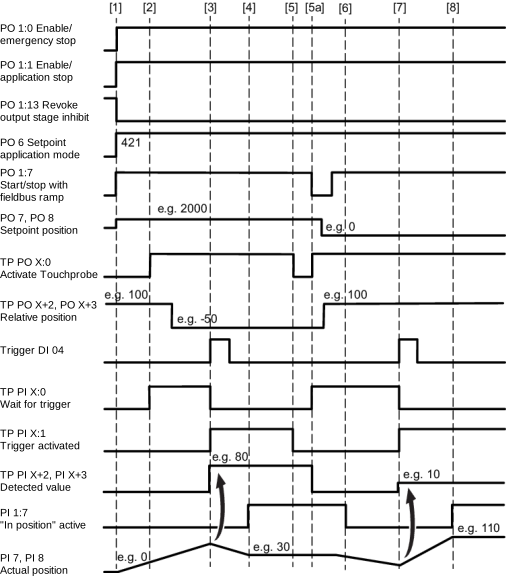
421 | Positioning absolute – Touchprobe remaining distance with sign (FCB 10) | |
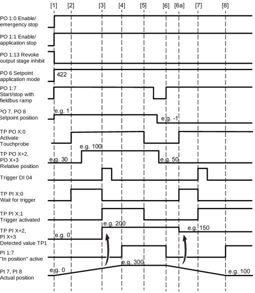
422 | Positioning endless – Touchprobe remaining distance in direction of travel (FCB 10) | |
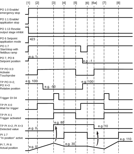
423 | Positioning endless – Touchprobe remaining distance with sign (FCB 10) | |
Brake test | 700 | Brake test – static (FCB 21) |
Synchronous operation | 1000 | Synchronous operation (FCB 10) |
1001 | Synchronous operation – adjustment absolute (FCB 10) | |
1002 | Synchronous operation – adjustment modulo positive (FCB 10) | |
1003 | Synchronous operation – adjustment modulo negative (FCB 10) | |
1004 | Synchronous operation – adjustment modulo short distance (FCB 10) | |
The following chapters provide a cycle diagram for each operating mode to help you better understand the operating principle. They also provide a process sequence with a description of the signals to be set and of the signal states.
- Requirements for cycle diagrams
- Jog – position-controlled (100)
- Jog – speed-controlled (101)
- Speed (200)
- Referencing – offset configured (300)
- Referencing – offset fieldbus (301)
- Positioning – absolute (400)
- Positioning – relative (401)
- Positioning – modulo positive (402)
- Positioning – modulo negative (403)
- Positioning – modulo short (404)
- Positioning absolute – Touchprobe remaining distance in direction of travel (420)
- Positioning absolute – Touchprobe remaining distance with sign (421)
- Positioning endless – Touchprobe remaining distance in direction of travel (422)
- Positioning endless – Touchprobe remaining distance with sign (423)
- Synchronous operation (1000)
- Synchronous operation – adjustment (1001 – 1004)