Connecting the MDE90A DC/DC-converter module to the energy storage system
- Make sure that the requirements from the chapter Discharging energy storage units before service work are implemented.
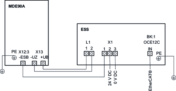
- Make the PE connection with a cable cross section of at least 16 mm2 directly at the PE ground busbar.
- Connect the terminal X13: +VB terminal of the MDP92A device with an appropriate conductor with double insulation, e.g. single 600-O VDE U0/U 600/1000 V with a cable cross section of 35 mm2 with the DC choke L1 terminal 1.
- Connect the terminal X13: -VDCL terminal of the MDE90A device with an appropriate conductor with double insulation. E.g. single 600-O VDE U0/U 600/1000 V with a cable cross section of 35 mm2 with the DC choke L1 terminal "2".
- Lay an appropriate conductor with double insulation with a cross section of 1.5 mm2 to 6.0 mm2 between the X12:3 (-ESB) connection on the MDE90A and terminal X1:1 (ES-) of the energy storage system.
- Connect a control cable for DC 24 V supply to connection X1: 2 (DC 24 V) and X1: 3 (DC 0 V). Match the cross section of this cable to the fusing.
- Connect the last existing bus participant to the "IN" input of the BK1 bus coupler. Use the 5-meter cable with the part number 18179983, or alternatively the 10-meter cable with the part number 18179991.
For the double cabinet variant, perform all of the connections to the basic cabinet specified above. You do not need any connections to the expansion cabinet.