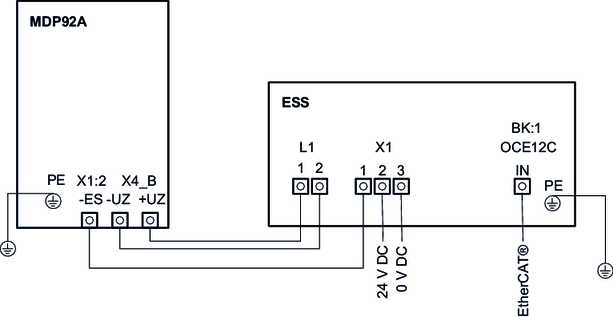
Connecting the MDP92A power supply module to the energy storage system
- Make sure that the requirements from the chapter Discharging energy storage units before service work are implemented.
- Make the PE connection with a cable cross section of at least 16 mm2 directly at the PE ground busbar.
- Connect the terminal X4_B: +VDCL terminal of the MDP92A device with an appropriate conductor with double insulation, e.g. single 600-O VDE U0/U 600/1000 V with a cable cross section of 35 mm2 with the DC choke L1 terminal 1.
- Connect the terminal X4_B: -VDCL terminal of the MDP92A device with an appropriate conductor with double insulation, e.g. single 600-O VDE U0/U 600/1000 V with a cable cross section of 35 mm2 with the DC choke L1 terminal 2.
- Lay an appropriate conductor with double insulation with a cross section of 1.5 mm2 to 6.0 mm2 between the X1:2 (-ES) connection on the MDP92A and terminal X1:1 (ES-) of the energy storage system.
- Lay a control cable for DC 24 V supply to connection X1:2 (DC 24 V) and X1:3 (DC 0 V). Match the cross section of this cable to the fusing.
- Connect the last existing bus participant to the "IN" input of the BK1 bus coupler. Use the 5-meter cable with the part number 18179983, or alternatively the 10-meter cable with the part number 18179991.