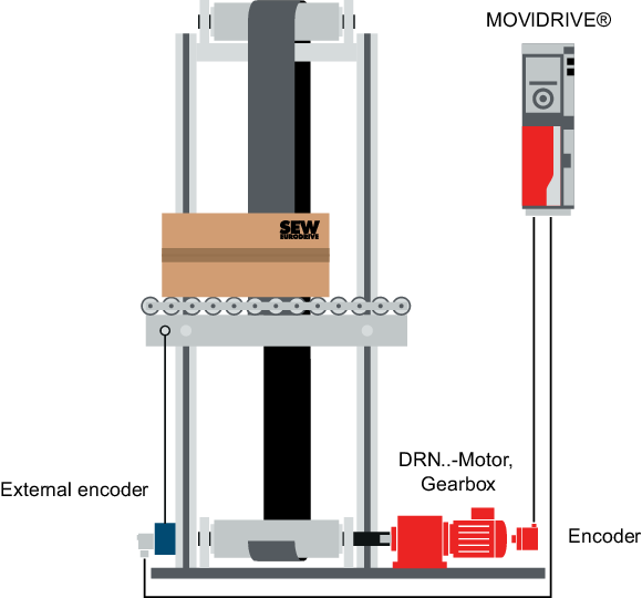
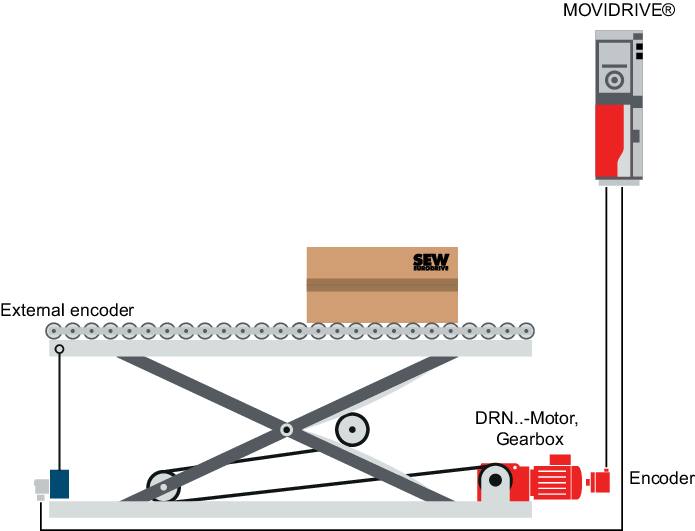
Combined encoder evaluation
If the position of the motor encoder does not clearly reflect the position of the system, a second encoder (distance encoder) can be used directly on the system.
Examples
- The drive motor of a storage/retrieval system can slip on the rail (slip condition). An additional laser encoder determines the actual position of the storage/retrieval system.
- A lifting drive lifts a lifting cage via a belt. Depending on the weight of the load, the belt lengthens. An additional draw-wire encoder determines the actual position of the lifting cage.
- Due to scissor mechanics, the table height of a scissor lift table does not linearly match the position of the motor encoder. An additional draw-wire encoder determines the actual position of the table height.
The resolution per path of the distance encoder is significantly lower than that of the motor encoder. If the position is controlled on the distance encoder, the stiffness of the control must be lowered. This results in lower control dynamics and more time to the target position.
The combined encoder evaluation collates the information from the motor encoder with the information from the distance encoder and makes it possible to adjust the position to that determined by the distance sensor, with the stiffness that a motor encoder would provide. This results in very dynamic positioning control; the system gets to the target much faster. Position deviations are compensated for very quickly.
The combined encoder evaluation is included in the firmware of the inverters. SEW-EURODRIVE recommends activating the combined encoder evaluation for applications with distance encoders.
