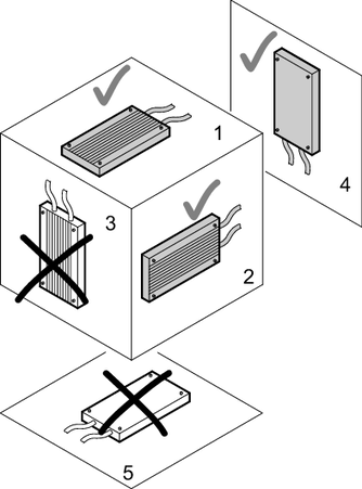
Permitted installation of braking resistors
The surfaces of the resistors become very hot if loaded with nominal power. The installation location of the resistor must be designed in accordance with the high temperatures. For this reason, braking resistors are usually mounted on the control cabinet roof.
The following minimum clearances must be observed for convection cooling depending on the continuous braking power and the mounting type.
Continuous braking power at 100% cdf | Mounting type | Lateral clearance or clearance between resistors in mm | Downward | Upward |
|---|---|---|---|---|
Up to 1 kW | Horizontal | 200 | 0 | 350 |
Vertical | 150 | 250 | 300 | |
Up to 10 kW | Horizontal | 300 | 0 | 650 |
Vertical | 250 | 350 | 600 | |
Up to 22 kW | Horizontal | 400 | 0 | 750 |
Vertical | 350 | 400 | 700 | |
Up to 44 kW | Horizontal | 500 | 0 | 850 |
Vertical | Not permitted | Not permitted | Not permitted |
NOTICE
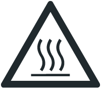
Overheating of the braking resistor.
Non-permissible installation might lead to heat build-up in the braking resistor due to reduced convection. A tripping temperature contact or an overheated braking resistor can lead to a system standstill.
Observe the following permitted mounting positions when installing the resistors:
- Grid resistor
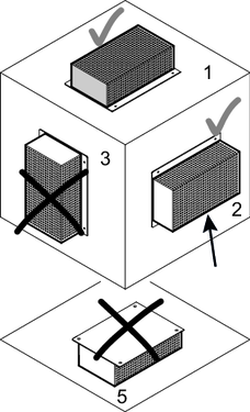
- Wire resistor
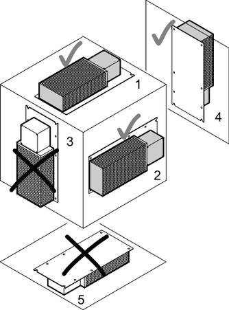
- Flat type resistor