Device structure of MDP92A-0250-503-4-S00 power supply module with controlled DC link voltage
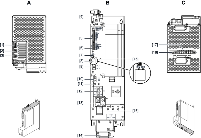
A: View from top | B: View from front | C: View from bottom | |||
[1] | X7: Braking resistor temperature monitoring | [4] | Shield terminal | [17] | X1: Line connection, braking resistor, measuring input for external energy storage unit, MDS90A-.. connection |
[2] | X30 OUT: System bus | [5] | X20: Digital inputs/outputs | [18] | Terminal screw for TN/TT systems |
[3] | X30 IN: System bus | [6] | X33: Interface for external energy storage unit | ||
| [7] | EtherCAT® ID switch |
|
| |
|
| [8] | 7-segment display |
| |
|
| [9] | X31: SEW‑EURODRIVE Service interface |
|
|
|
|
|
|
|
|
|
| [10] | X5: 24 V supply voltage connection |
|
|
|
| [11] | PE connection |
|
|
|
| [12] | X4: DC link busbar |
|
|
|
| [13] | X4_B: DC link connection for external energy storage units |
|
|
|
| [14] | Shield terminal |
|
|
|
| [15] | Power LED |
|
|
|
| [16] | PE connection at housing |
|
|
