Inverters of size 4 and larger
The following 3 connections exist:
Connection 1 | Connection 2 | Connection 3 |
|---|---|---|
|
|
|
[1] | Line contactor | [4] | PLC |
[2] | Braking resistor | [5] | Inverter |
[3] | Internal temperature switch or overload relay |
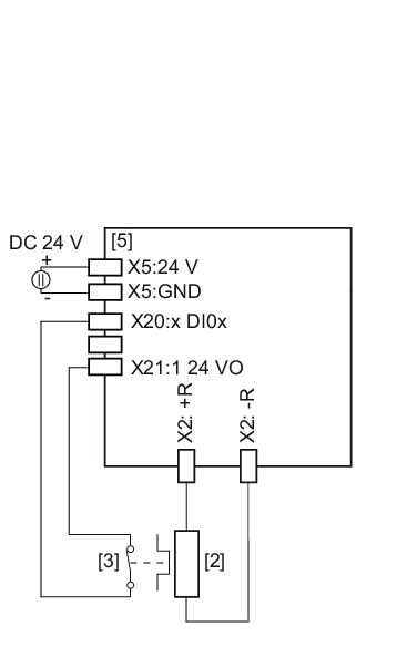
Connection 1
INFORMATION

When using connection variant 1 (connection of braking resistor without line contactor), the inverter must be supplied with external DC 24 V.
INFORMATION
When circuit 1 is used, there is no galvanic isolation from the grid. The device is not de-energized. If it is necessary to de-energize the device, e.g., for electrical work, you have to switch it off with a main switch, for example. The switch-off design is always done system-specific depending on the specific application considering the applicable regulations.
The signal contact is evaluated in the inverter. The digital input of the inverter used for the evaluation must be parameterized to the "External braking resistor fault" function
- A response by the PLC is not required.
- It is not necessary to disconnect the line connection using an external switching device.
- If an internal short circuit in the brake chopper is detected by the inverter, the inverter interrupts the energy supply by inhibiting the rectifier.
- The inverter switches to "Output stage inhibit".
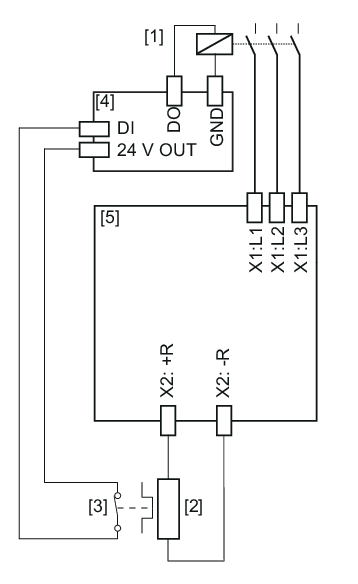
Connection 2
The signal contact is only evaluated in the PLC.
If the internal temperature switch responds, note the following:
- The PLC must disconnect the power supply.
- There is no direct response in the inverter.
With connection 2, it is possible that the PLC finishes the current travel cycle although the thermal circuit breaker has tripped. Only then is the power supply disconnected. In this case, the residual braking energy WRest = PBRnom × 20 s must not be exceeded.
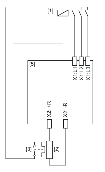
Connection 3
The signal contact directly affects the line contactor.
If the internal temperature switch responds, note the following:
- A response by the PLC is not required.
- There is no direct response in the inverter.
