Setting the speed limit
Before the torque setpoint is transferred from the setpoint source to the control mode, it passes through various limitations. In order not to exceed the speed limit (nmax), the torque is continuously reduced along a straight line near the speed limit.
The range of the internal torque limiting is calculated according to the following formula:
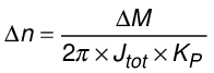
Δn | Width of the area of the internal torque limiting [Δn] = s-1 referred to the speed at the motor shaft |
ΔM | Difference of the torque limits [ΔM] = Nm referred to the torque at the motor shaft |
Jtot | Total moment of inertia of the drive (sum of the mass moments of inertia of the motor, brake, gear unit, and load). [Jtot] = kgm2 referred to the speed at the motor shaft |
KP | P gain of the speed controller [KP] = s-1 |
Example:
In the speed range 0 – speed setpoint (nset), a motor should reach the torque specified by process data word PO 10. To ensure that the internal torque limiting does not happen prematurely, the following maximum speed must be specified by process data word PO 2:
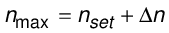
nmax | Maximum speed [nmax] = s-1 |
nset | Speed setpoint [nset] = s-1 |
Δn | Width of the area of the internal torque limiting [Δn] = s-1 referred to the speed at the motor shaft |
The following figure shows the behavior of the drive:

Q1 to Q4 | Quadrant |
n1 | Maximum positive speed |
n2 | Maximum negative speed |
Δn | Width of the area of the internal torque limiting [Δn] = s-1 referred to the speed at the motor shaft |
M1 | Maximum positive torque |
M2 | Maximum negative torque |
ΔM | Difference of the torque limits [ΔM] = Nm referred to the torque at the motor shaft |
The torque specified by process data word PO 10 is effective until the speed setpoint reaches the torque limiting range (Δn). In the range, the torque is continuously limited internally up to the maximum speed (n1 or n2) specified by process data word PO 2.
INFORMATION