Inverter sizes 0S, 0L
The following 3 connections exist:
Circuit 1 | Circuit 2 | Circuit 3 |
|---|---|---|
|
|
|
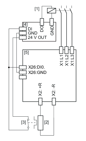
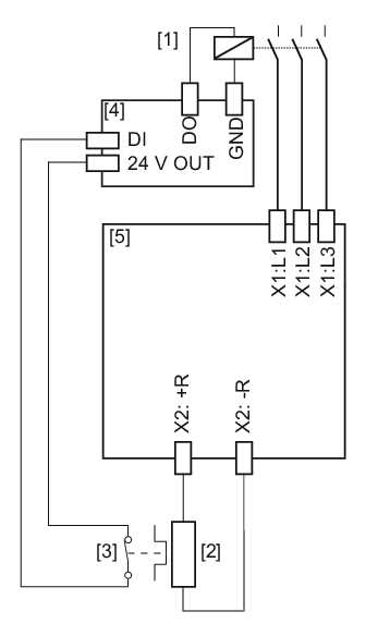
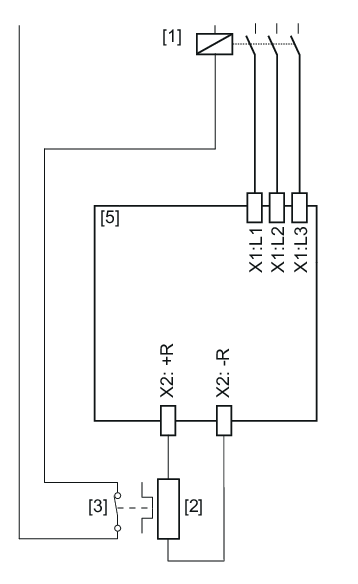
[1] | Line contactor | [4] | PLC |
[2] | Braking resistor | [5] | Inverter |
[3] | Internal temperature switch or overload relay |
Connection 1
INFORMATION

When connection 1 is used, the reference potential GND of the digital inputs on the PLC must be the same as the reference potential of the inverter.
The signal contact is evaluated in the inverter and in the PLC. The digital input of the inverter used for the evaluation must be parameterized to the "External braking resistor fault" function.
If the internal temperature switch responds, note the following:
- The PLC must disconnect the power supply.
- The inverter switches to "Output stage inhibit".
Connection 2
The signal contact is only evaluated in the PLC.
If the internal temperature switch responds, note the following:
- The PLC must disconnect the power supply.
- There is no direct response in the inverter.
With circuit 2, it is possible that the PLC finishes the current travel cycle although the thermal circuit breaker has tripped. Only then is the power supply disconnected. In this case, the residual braking energy Wres = PBR_nom × 20 s must not be exceeded.
Connection 3
The signal contact directly affects the line contactor.
If the internal temperature switch responds, note the following:
- A response by the PLC is not required.
- There is no direct response in the inverter.
