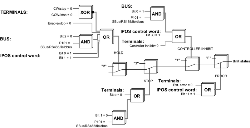
Linking safety-relevant control commands
Basically, the control commands
- CONTROLLER INHIBIT
- RAPID STOP / STOP
- STOP
- ENABLE
can be activated simultaneously using the set control signal source, the digital inputs, and the IPOSplus® control program. To link these control functions under safety-relevant aspects, the individual control commands are prioritized. For enabling the frequency inverter, for example, the following figure shows that all three processing blocks (terminal processing, control word processing, and IPOSplus® program) have to generate the enable. As soon as one of the three processing blocks triggers a control command of higher priority (such as STOP or CONTROLLER INHIBIT), the higher prioritized command will become effective.
After switching on the frequency inverter, IPOSplus® generally issues the control command ENABLE so that the drive can be controlled immediately even without the IPOSplus® program.
The digital inputs will generally remain active even if the frequency inverter is controlled via the process data (P101 control signal source = RS485/FIELDBUS/SBus). Safety-relevant functions, such as controller inhibit and enable are equally processed by the terminal strip and the fieldbus. This means the frequency inverter must have first been enabled at the terminals to control via fieldbus. All other functions that can be activated via terminals and the control word, will be processed with an OR function. The following figure shows the device status depending on the various control signal sources (terminals, bus, or IPOS® control word).

For safety reasons, the basic control block is defined in such a way that the frequency inverter with the control word setting 0000hex will assume the state No enable because all commercially available fieldbus master systems will reset the outputs to 0000hex in the event of a fault. In this case, the frequency inverter will execute a rapid stop and then activate the mechanical brake.
