Installing submounting resistor BW120-001, BW100-002/M
Size 1 and 2 inverters can be installed in the control cabinet together with a braking resistor. The braking resistor is located on the rear panel of the inverter and therefore has the same mounting hole pattern as the inverter.
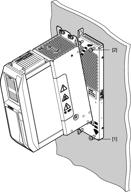
Note that the retaining screws [1] and [2] must be 20 cm longer for installation with a braking resistor.

- Place the braking resistor at the desired position in the control cabinet as shown in the figure, and screw in the 4 retaining screws [1] and [2] without tightening them.
- Place the inverter with the slotted holes in the device base plate onto the retaining screws [1] from the top.
- Push the inverter backwards to insert the retaining screws [2] into the upper holes in the device base plate.
- Lower the inverter.
- Install the shield plate; see the chapter Control cabinet installation.
- Tighten the retaining screws [1] and [2].
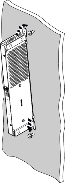
The submounting resistor can be installed next to an inverter, see the following figure. The hole distance of the submounting braking resistor must be larger than the hole distance of the inverter.

