Configuration
- For the following application example, a MOVI-C® CONTROLLER is required as hardware. The real axes used are simulated.
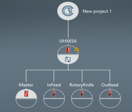
- In MOVISUITE® in "Planning" mode, create a project with a MOVI-C® CONTROLLER, one virtual ("master") and three real axes ("InFeed", "RotaryKnife", "OutFeed"). In the application example, the virtual axis acts as the master axis.
- Configure a valid drive train without user units for the real axes.
- Assign the following software modules to the axes:
- Master: MOVIKIT® Gearing
- InFeed: MOVIKIT® FilmFeeder
- RotaryKnife: MOVIKIT® RotaryKnife
- OutFeed: MOVIKIT® Gearing
- Configure the user unit for the "master" axis:
- User unit: User-defined unit: Cycle
- Position: Cycle, number of decimal places: 6
- Speed: Cycle/min, number of decimal places: 4
- Acceleration: Cycle/(min*s), number of decimal places: 2
- Configure the cycle limit for the "master" axis.
- Modulo minimum: 0 cycles
- Modulo maximum: 1 cycle
- Configure the user unit for the "InFeed" axis:
- User unit: User-defined unit: mm
- 1 revolution = 100 mm
- Position: mm, number of decimal places: 3
- Speed: mm/s, number of decimal places: 4
- Acceleration: mm/(s*s), number of decimal places: 2
- Configure the user unit for the "RotaryKnife" axis:
- User unit: Degree
- Position: Degrees, number of decimal places: 3
- Speed: Degrees/s, number of decimal places: 4
- Acceleration: Degree/(s*s), number of decimal places: 2
- Check the configuration of the following cycle limit for the "RotaryKnife" axis.
- Modulo minimum: 0 degrees
- Modulo maximum: 360 degrees
- Configure the user unit for the "OutFeed" axis:
- User unit: User-defined unit: mm
- 1 revolution = 100 mm
- Position: mm, number of decimal places: 3
- Speed: mm/s, number of decimal places: 4
- Acceleration: mm/(s*s), number of decimal places: 2
- Configure the software module of the "master" axis:
- Fieldbus interface – Activate fieldbus connection
- Fieldbus interface – Start address: 1
- Configure the software module of the "InFeed" axis:
- Basic settings – Activate simulation
- Synchronous operation – Master source: Configured axis
- Synchronous operation – Name of master axis: Master
- Fieldbus interface – Activate fieldbus connection
- Fieldbus interface – Start address: 9
- Configure the software module of the "RotaryKnife" axis:
- Basic settings – Activate simulation
- Electronic cam – Master source: Configured axis
- Electronic cam – Name of master axis: Master
- Rotary knife – Type of master axis: Modulo axis – Cyclic position
- Fieldbus interface – Activate fieldbus connection
- Fieldbus interface – Start address: 25
- Configure the software module of the "OutFeed" axis:
- Basic settings – Activate simulation
- Synchronous operation – Master source: Configured axis
- Synchronous operation – Gear ratio master/slave numerator: 160 mm
- Synchronous operation – Gear ratio master/slave denominator: 1 cycle
- Synchronous operation – Name of master axis: Master
- Fieldbus interface – Activate fieldbus connection
- Fieldbus interface – Start address: 41


- The configuration results in the following process data assignment:

- Switch to "Startup" mode.
- Connect the MOVI-C® CONTROLLER in the project view with the MOVI-C® CONTROLLER in the network view, and then update the IEC project.
