Connection of process data
For processing the touchprobe function, the following control and status information must be mapped to the free process data words in the inverter:
- Touchprobe position
- Touchprobe counter
- "Activate" control bit
- "Active" status bit
Proceed as follows:
- The process data profile was extended to include additional process data words. For instructions, refer to the chapter Extending the process data profile.
- In MOVISUITE®, click the software module.
- The configuration menus of the software module are displayed.
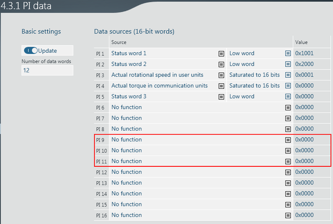
- Under "Functions" in the main menu, open the "Actual values" menu and its submenu "PI data".
- To connect the touchprobe position, define "Low word" of the position for "Touchprobe 1/detected value" as the source for "PI 9".
- To connect the touchprobe position, define "High word" of the position for "Touchprobe 1/detected value" as the source for "PI 10".
- To connect the touchprobe counter, define "Saturated to 16 bits" for "Touchprobe 1/trigger – counter" as the source for "PI 11".
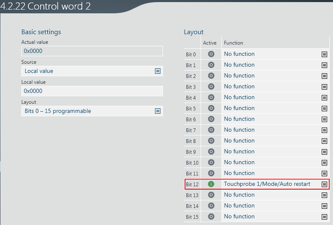
- Under "Functions" in the main menu, open the "Setpoints" menu and its submenu "Control word 2".
- To connect "Activate touchprobe" control, define the function "Touchprobe 1/Mode/Auto restart" for "Bit 12".
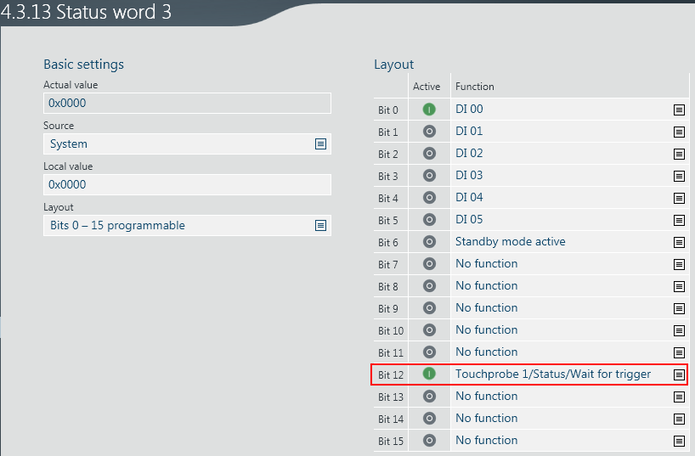
- Under "Functions" in the main menu, open the "Setpoints" menu and its submenu "Control word 3".
- To connect the "Touchprobe active" feedback, define the function "Touchprobe 1/Status/Wait for trigger" for "Bit 12".


