Configuration – PID (ST_Config_PID)
Variable name | Description |
|---|---|
lrFeedbackSignalScalingU1 lrFeedbackSignalScalingP1 lrFeedbackSignalScalingU2 lrFeedbackSignalScalingP2 | Data type – LREAL |
Scaling of the actual value signal: For scaling the actual value signal, 2 pair of values must be specified which result from the U1/U2 input signal with the corresponding tension/dancer position P1/P2. A positive characteristic curve is displayed in this figure. For a negative characteristic curve, enter a value for P1 that is greater than P2.
| |
uiFeedbackSignalFilterTime | Data type – UINT |
Filter time (VZ1 filter) in ms of the scaled actual value signal | |
lrKP | Data type – LREAL |
Controller gain (P component) Active if xKPdynOFF = "TRUE" to switch off the dynamic gain during startup and to test different values. | |
lrTN | Data type – LREAL |
Integral time (I component) in ms High values (e.g. 60 000 ms) have a very small influence and small values (e.g. 1000 ms) a very large influence. | |
lrTV | Data type – LREAL |
Derivative time (D component) in ms INFORMATION: 0 ms deactivates this component. | |
xPIDreset | Data type – BOOL |
| |
uiLimiterPos uiLimiterNeg | Data type – UINT |
Positive or negative limitation of the PID controller output signal. The values must be specified in the following unit depending on the operating mode:
| |
uiWeightingPID | Data type – UINT |
Weighting of the PID controller output signal in % to decrease or increase the influence INFORMATION: 100% corresponds to the factor 1. | |
uiWeightingPreCtrl | Data type – UINT |
Weighting of the precontrol (current path speed) in % for the closed-loop dancer position control operating mode and closed-loop tension control via setpoint speed INFORMATION: 100% corresponds to the factor 1. | |
uiLineSpeedFilterTime | Data type – UINT |
Filter time (VZ1 filter) of the input signal lrActualLineSpeed in ms | |
xKPdynOFF | Data type – BOOL |
| |
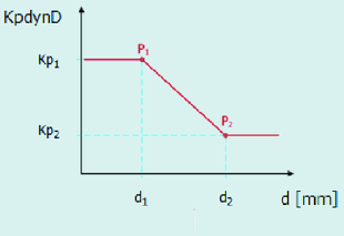
lrKpDynDx1 lrKpDynD1 lrKpDynDx2 lrKpDynD2 | Data type – LREAL |
Parameterization of the diameter-dependent controller gain: 2 pairs of values resulting from the diameters d1 and d2 (lrKpDynDx1 and lrKpDynDx2) with the corresponding gain factors Kp1 and Kp2 (lrKpDynD1 and lrKpDynD2). By default, the controller gain must be reduced with an increasing diameter. A negative characteristic curve is displayed in this figure. For a positive characteristic curve, enter a value for Kp1 (lrKpDynD1) that is smaller than Kp2 (lrKpDynD2).
The total controller gain results from the product of the two dynamic components: | |
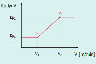
lrKpDynVx1 lrKpDynV1 lrKpDynVx2 lrKpDynV2 | Data type – LREAL |
Parameterization of the speed-dependent controller gain: 2 pairs of values resulting from the path speeds v1 and v2 (lrKpDynVx1 and lrKpDynVx2) with the corresponding gain factors Kp1 and Kp2 (lrKpDynV1 and lrKpDynV2). By default, the controller gain must be increased with an increasing speed. A positive characteristic curve is displayed in this figure. For a negative characteristic curve, enter a value for Kp1 (lrKpDynV1) that is greater than Kp2 (lrKpDynV2).
The total controller gain results from the product of the two dynamic components: |


