Integrating and configuring an inverter in the PROFIBUS network
The inverter must be added to the TIA Portal project, connected with the PLC, and configured.
During configuration, the inverter is assigned a PROFIBUS address and process data with addresses.
Proceed as follows:
- The PROFIBUS address of the inverter is the address you have already set via the DIP switches of the fieldbus card (see PROFIBUS address).
- You have already downloaded the device description file () of the inverter from the SEW‑EURODRIVE homepage (www.sew-eurodrive.com) and saved it locally on the engineering PC.
- Start the TIA Portal and create a new TIA Portal project.
- Install the device description file in the TIA Portal.
- Add the PLC to the project. Enter the IP address parameters of the PLC and set the PROFIBUS fieldbus interface as the interface type.
- Insert the master system at the PROFIBUS fieldbus interface of the PLC.
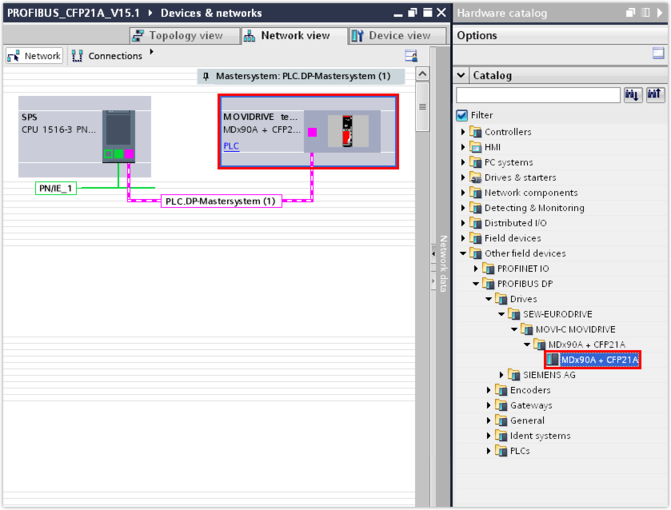
- Open the hardware catalog. Under [More field devices] > "PROFIBUS DP] > [Drives] > [SEW-EURODRIVE] > [MOVI-C MOVIDRIVE], select the entry for the MOVIDRIVE® technology application inverter and assign this entry in the network view of the PLC.
- In the inspector window (lower editor area), in the "PROFIBUS address" group, from the "Address" drop-down menu, select the PROFIBUS address of the inverter that you have set on the fieldbus card using the DIP switches.
- Assign a name to the inverter in the "General" group. This is the name under which the device is shown in the TIA Portal project.
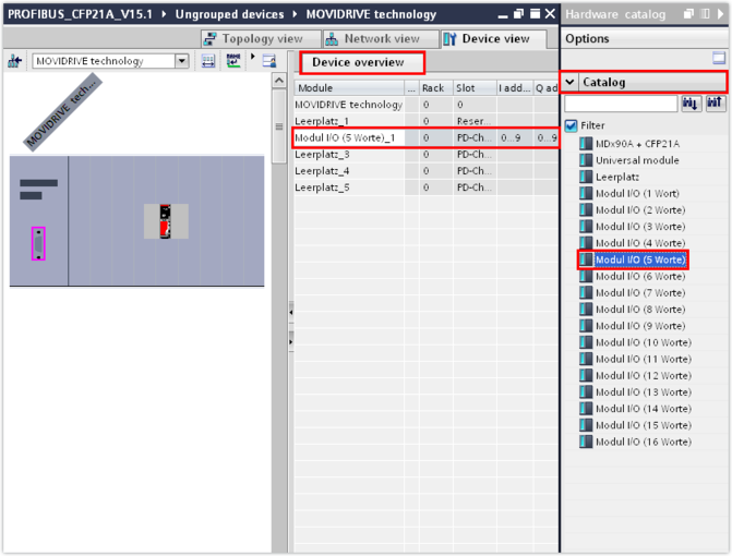
- In the device overview, right-click to open the context menu of the slot in which you want to insert the inverter (lower-level slave), and delete the existing empty space entry.
- Add the required number of process data words from the hardware catalog using drag and drop. Instead, you can add the process data words by double-clicking the module in the device overview. They will be inserted at the proper slot automatically.
- Load the project to the PLC using the programming interface used.
- Save the TIA Portal project.
INFORMATION

Slot 1 is reserved. You can add standard process data words to the device overview to slot 2 and higher.
For the amount of process data words currently set in the inverter, refer to the MOVISUITE® engineering software. For further information on the assignment of process data words, refer to the chapter Process data configuration.