Integrating and configuring MOVI‑C® CONTROLLER in PROFIBUS network
The MOVI‑C® CONTROLLER must also be added to the TIA portal project, connected to the PLC and configured.
During configuration, the MOVI‑C® CONTROLLER is assigned a PROFIBUS address and process data with addresses.
Proceed as follows:
- You already downloaded the device description file () of the MOVI‑C® CONTROLLER from the SEW-EURODRIVE homepage → www.sew-eurodrive.com and saved it on your computer (see chapter Installing device description file of the MOVI‑C® CONTROLLER).
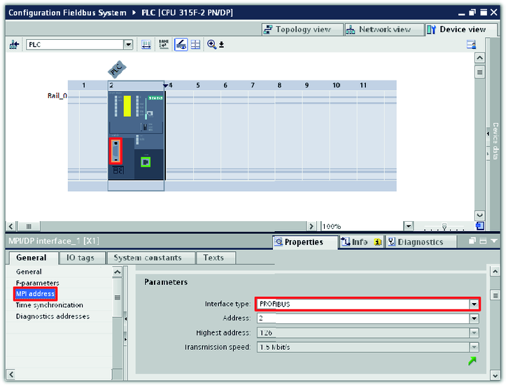
- Double-click the MPI/DP interface (orange colored).
- The interface properties are displayed in the inspector window (lower screen section).
- Select the PROFIBUS interface from the "Interface type" drop-down list in the "MPI address" group.
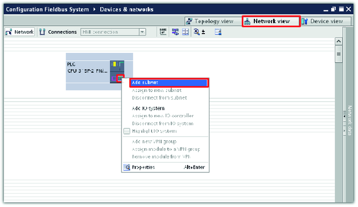
- Switch to network view in the hardware and network editor.
- Open the Ethernet interface context menu by right-clicking and add a subnetwork. The Ethernet interface is the connection between the MOVI‑C® CONTROLLER and the engineering PC.
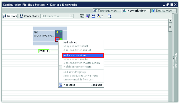
- Open the PROFIBUS interface (purple colored) context menu by right-clicking and add the master system.
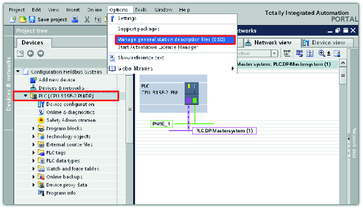
- Load the device description file to the TIA portal project.
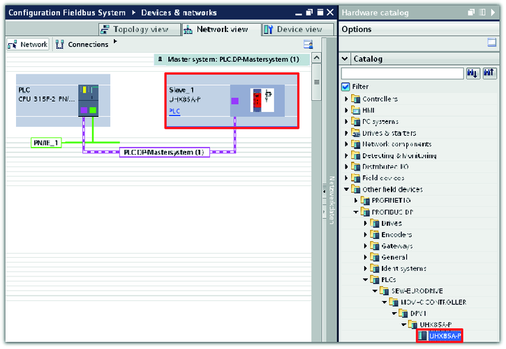
- Open the hardware catalog in the bar at the right side of the screen. Select the MOVI-C® CONTROLLER from the catalog and insert it at the end of the PROFIBUS branch using the drag-and-drop function. Assign the device to the suitable controller.
- In this example, the MOVI‑C® CONTROLLER in UHX85A-P device design is used and assigned to the controller with the device name "PLC".
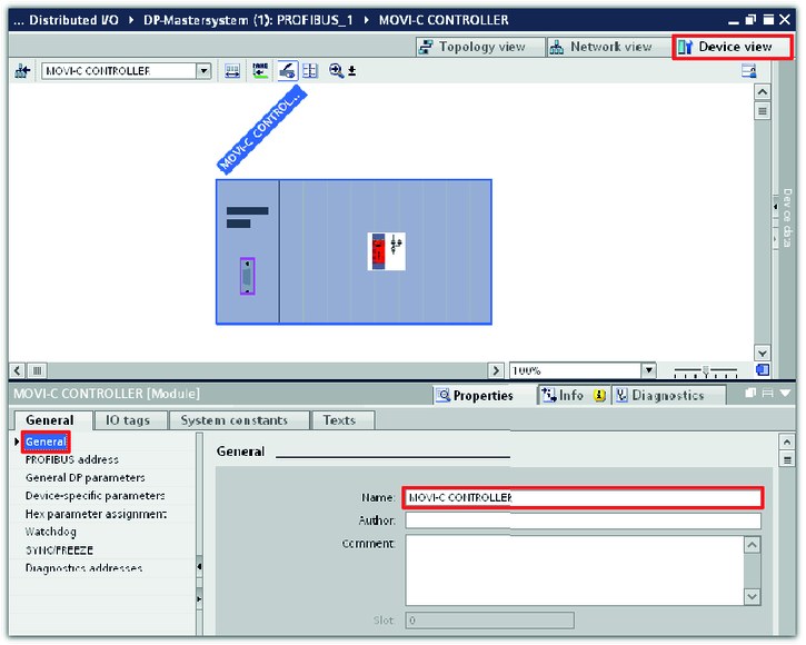
- To configure the MOVI‑C® CONTROLLER, double-click on the device.
- The device view is displayed.
- Enter a name for the MOVI‑C® CONTROLLER in the inspector window (lower editor section) in the "General" tab. The device is shown in the TIA portal project under this name.
- In this example, the project name "MOVI-C CONTROLLER" is used for the MOVI‑C® CONTROLLER.
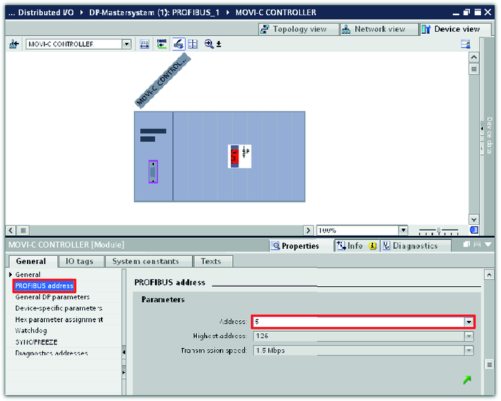
- Select the PROFIBUS address of the MOVI‑C® CONTROLLER from the "Address" drop-down list in the "PROFIBUS address" group.
- In this example, the PROFIBUS address of the MOVI‑C® CONTROLLER is 5.
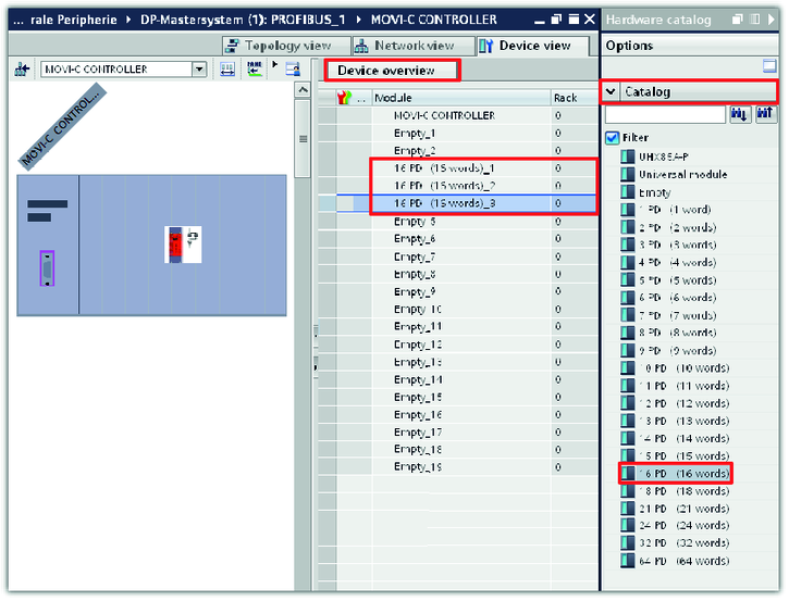
- Expand the device overview on the right side of the device view tab. Right-click to open the context menu of the slot in which you want to insert the lower-level slave and delete the existing entry.
- Open the hardware catalog in the bar at the right side of the screen. Select the number of process data words that are to be used for communication with lower-level slaves and add them to the device overview using the drag-and-drop function.
- In this example, 16 process data words are assigned to the each application inverter module (slaves of MOVI‑C® CONTROLLER) for communication.
INFORMATION

The first 2 slots are reserved for future safety applications.
You can add process data words to the device overview only to slot 3 and higher.