Connecting the MOVI‑C® CONTROLLER to the PROFIBUS network
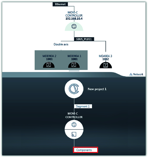
This examples explains how to connect a MOVI‑C® CONTROLLER to a PROFIBUS network. The following device topology was used in the example:
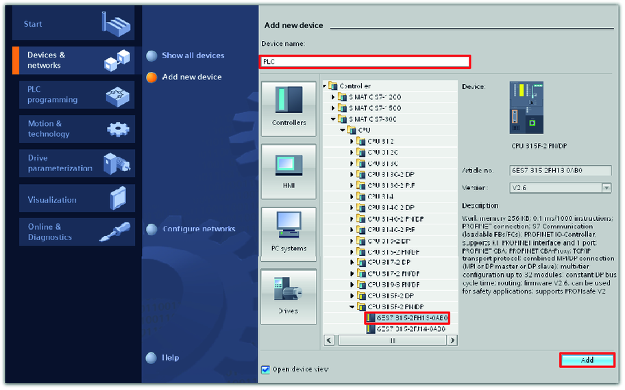
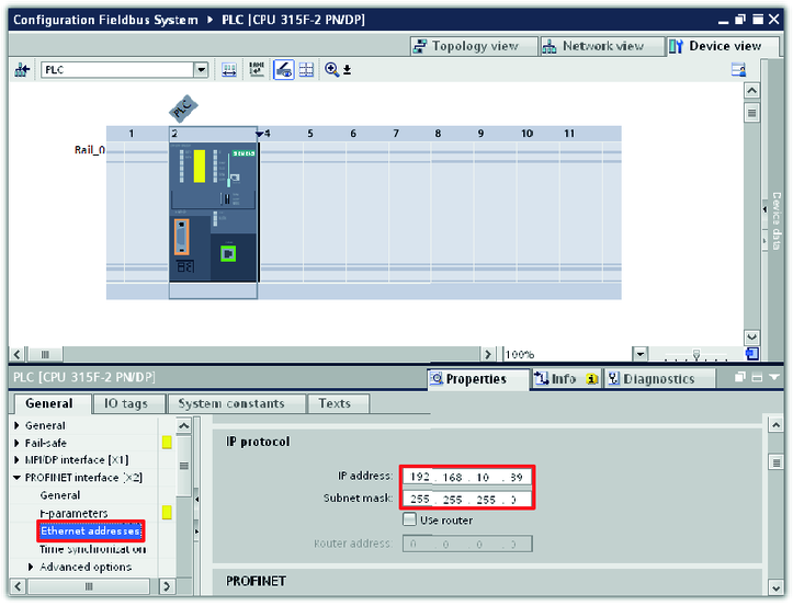
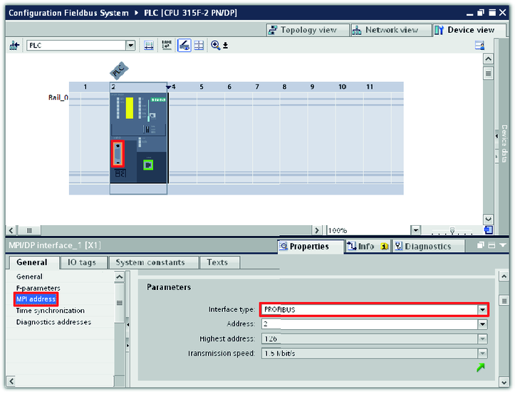
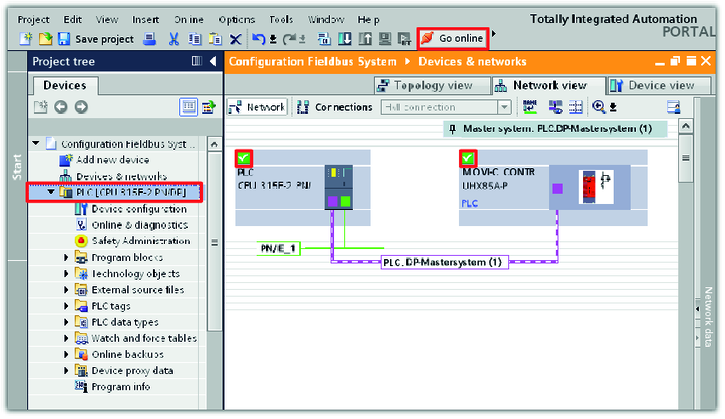
- SIMATIC S7‑300 higher-level controller with CPU 315F‑2 PN/DP
- MOVI‑C® CONTROLLER power, device design
- MOVIDRIVE® modular application inverter, MDD90A double-axis module
- MOVIDRIVE® modular application inverter, MDA90A single-axis module
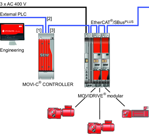
[1] | Engineering interface LAN 3 |
[2] | |
[3] | EtherCAT®/SBusPLUS interface LAN 2 |
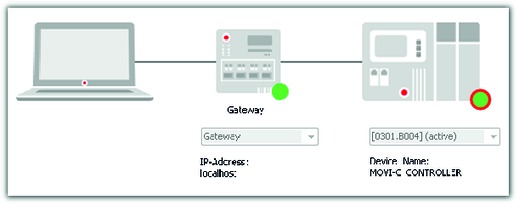
The PLC communicates with a lower-level MOVI‑C® CONTROLLER via the fieldbus interface [2]. The MOVI-C® CONTROLLER communicates with the lower-level application inverter via the EtherCAT®/SBusPLUS system bus [3]. The connection between the MOVI‑C® CONTROLLER and the engineering PC is realized via the engineering interface [1].
For configuration and startup of the devices, the following engineering software is used:
- MOVISUITE® for the MOVI‑C® devices from SEW‑EURODRIVE
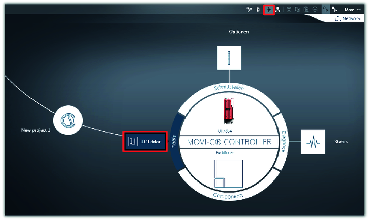
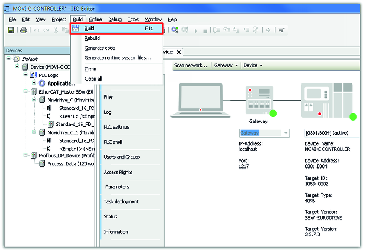
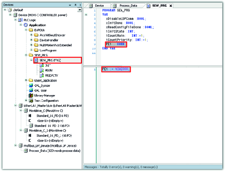
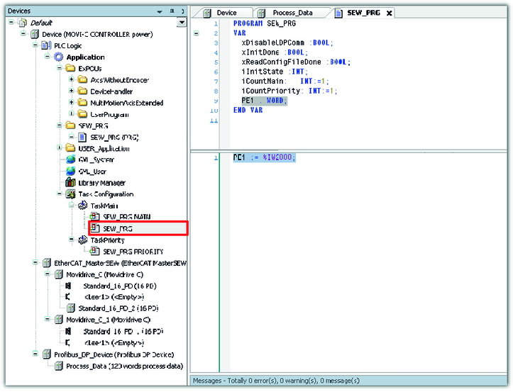
- MOVISUITE® has an integrated IEC editor to configure the MOVI‑C® CONTROLLER.
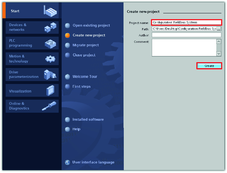
- TIA Portal (SIMATIC STEP 7) from Siemens for the PLC
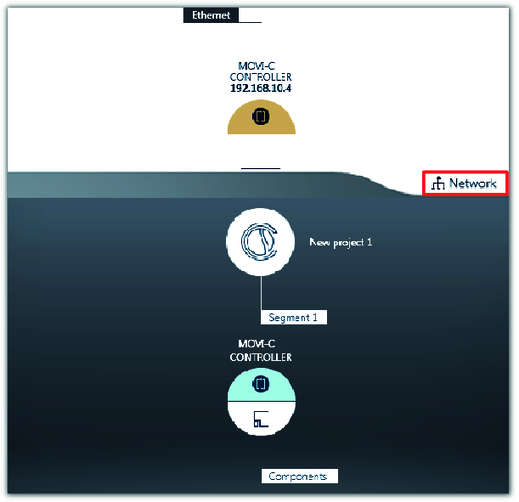
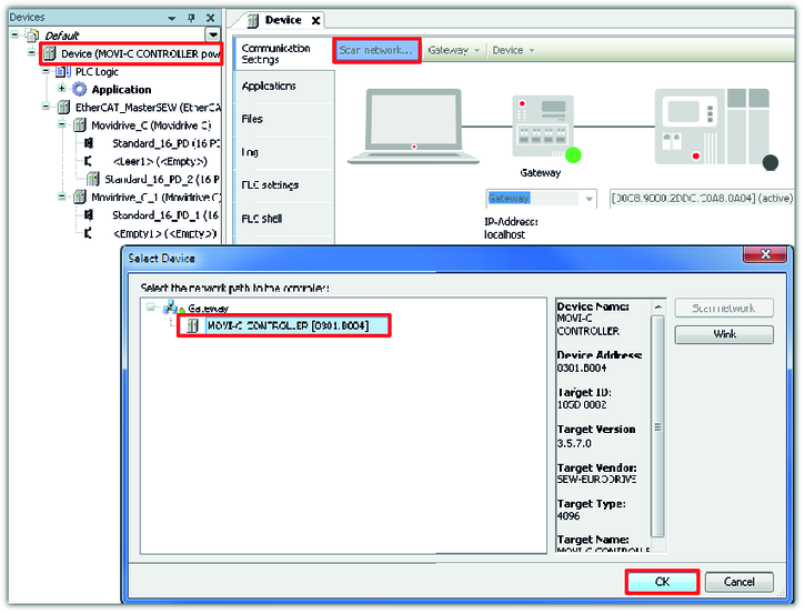
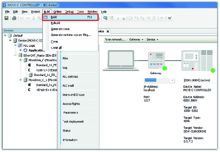
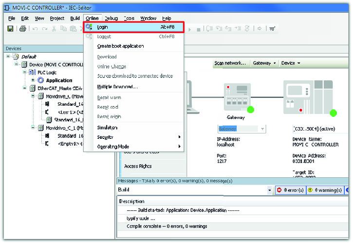
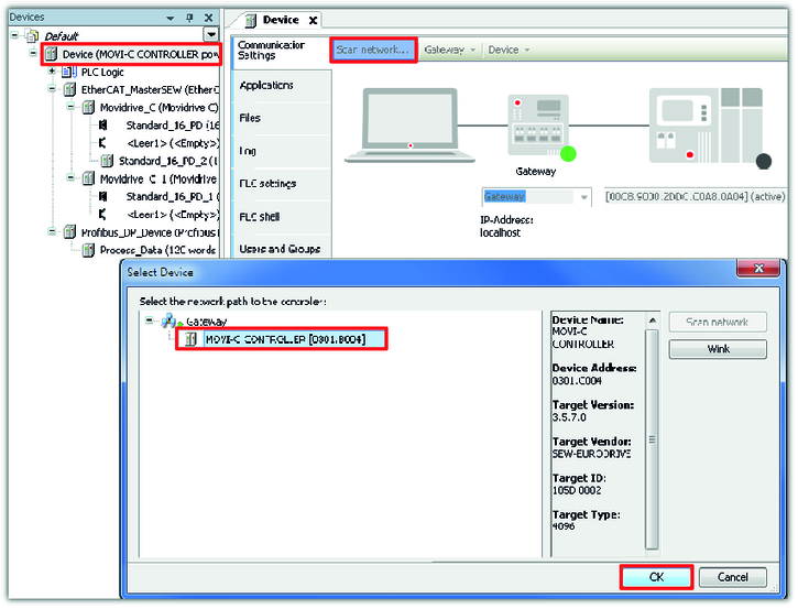
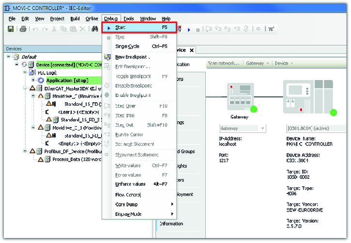
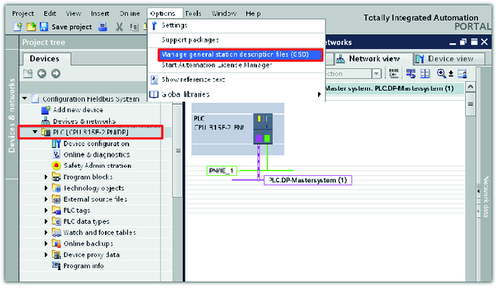
To connect the MOVI‑C® CONTROLLER to the PROFIBUS network, perform the following steps:
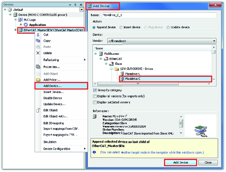
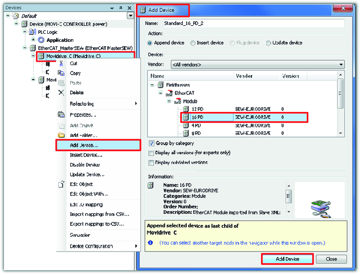
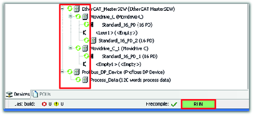
- Configuration of the EtherCAT®/SBusPLUS stations
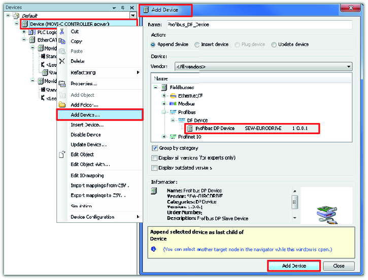
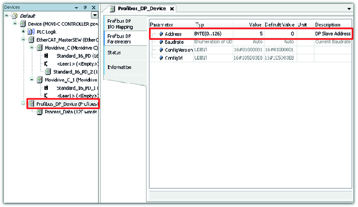
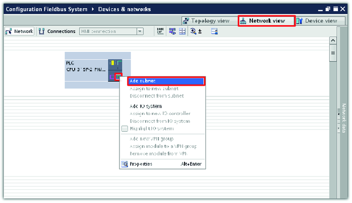
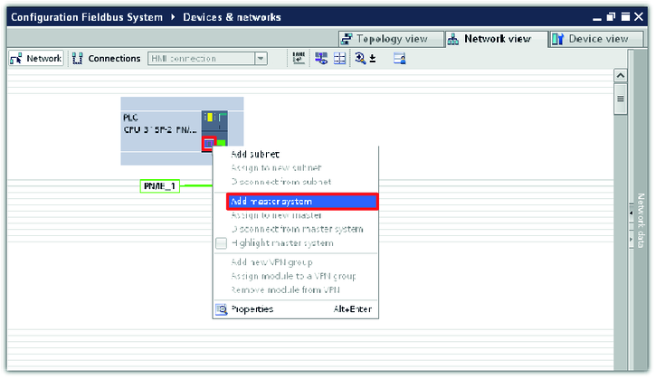
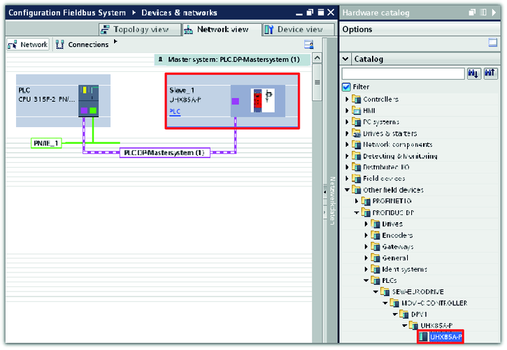
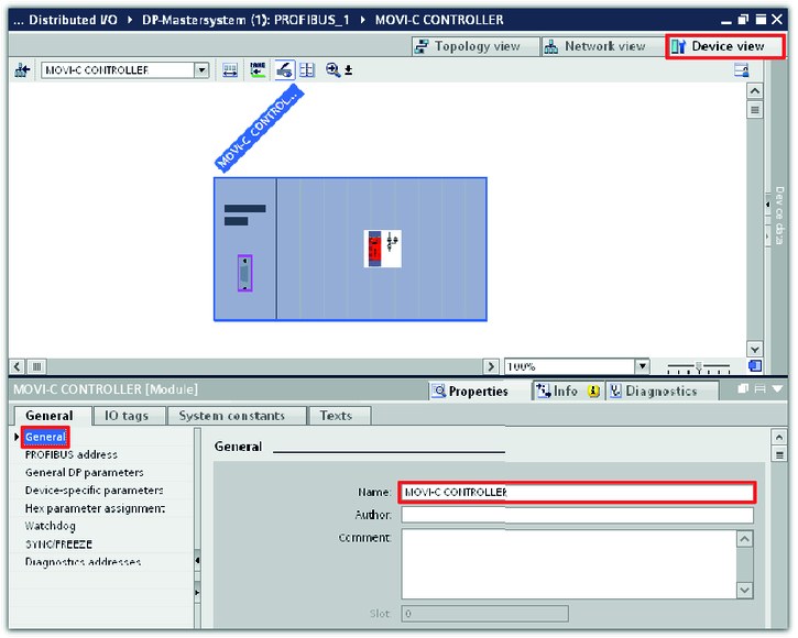
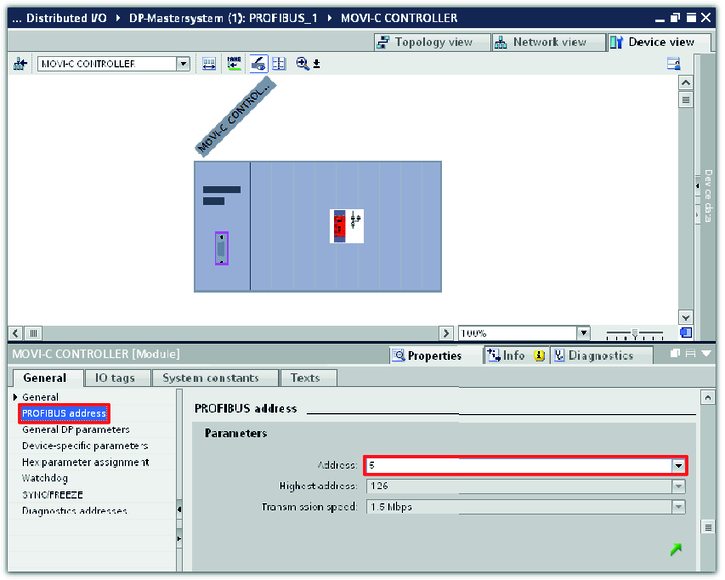
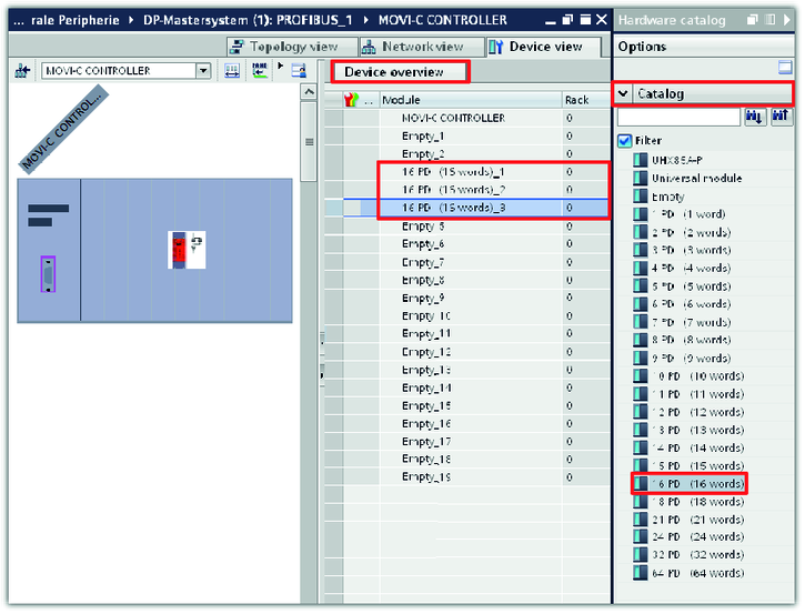
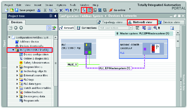
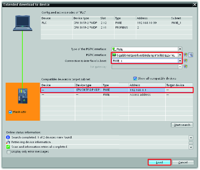
- Configuration of the fieldbus stations
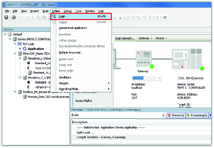
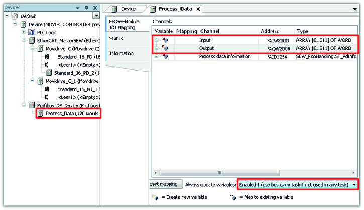
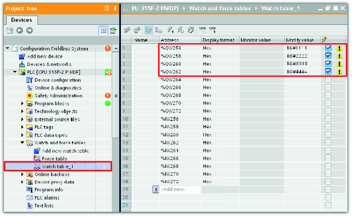
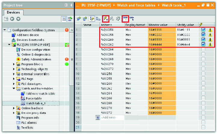
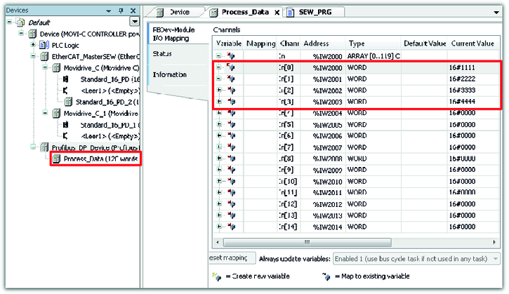
- Checking the process data communication
Additional information