MOVIMOT® inverter
The following figure shows the connection box and the MOVIMOT® inverter:
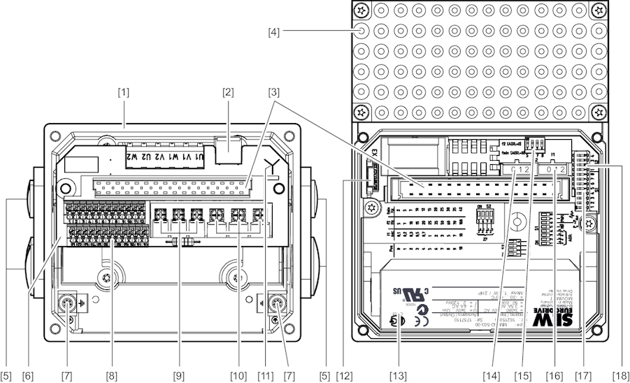
[1] | Connection box |
[2] | X10: Connector for the BEM/BES options |
[3] | Connection plug for the MOVIMOT® inverter |
[4] | MOVIMOT® inverter with heat sink |
[5] | Cable glands |
[6] | Connection unit with terminals |
[7] | Screw for PE connection ⍊ |
[8] | X5, X6: Electronics terminal strip |
[9] | X1: Connection for brake coil (motors with brake) or braking resistor (motors without brake) |
[10] | X1: Line connection L1, L2, L3 |
[11] | Identification of the connection type |
[12] | Drive ID module |
[13] | MOVIMOT® inverter nameplate |
[14] | Setpoint switch f2 (green) |
[15] | DIP switches S2/5 – S2/8 |
[16] | Switch t1 for integrator ramp (white) |
[17] | DIP switches S1/1 – S1/8 |
[18] | DIP switches S2/1 – S2/4 |
The following figure shows the top of the MOVIMOT® inverter:
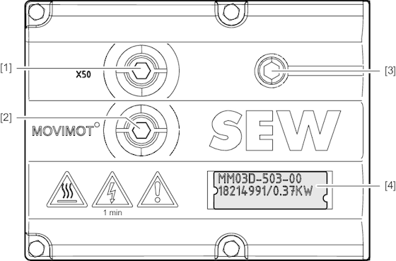
[1] | X50: Diagnostics interface with screw plug |
[2] | Setpoint potentiometer f1 with screw plug |
[3] | Status LED |
[4] | Identification tag |
