Brake chopper terminal assignment
The following figure shows the terminals of the brake chopper.
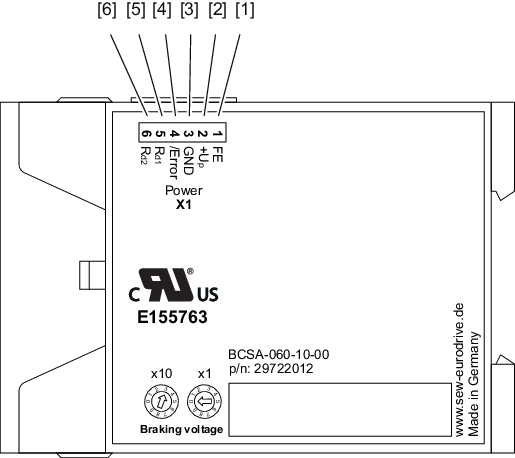
No. | Name | Function |
|---|---|---|
1 | FE | Functional earth |
2 | +48 V/L2 (+Up) | Power supply L2 (+Up) |
3 | 0 V48/N2 (GND) | Power supply reference potential N2 (GND) |
4 | DO (/Error) | Output for error message (negative logic) |
5 | BR (Rd1) | Connection for braking resistor |
6 | BR (Rd2) | Connection for braking resistor |
