Size 7
Terminal | Contact | Function | |
|---|---|---|---|
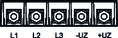
| X1:L1 | L1 | Precharging unit connection |
X1:L2 | L2 | ||
X1:L3 | L3 | ||
X1:-UZ | -UZ | DC link connection on rectifier side | |
X1:+UZ | +UZ | ||
| PE | Protective earth connection | |
| -UZ* | -UZ | DC link connection capacitor side |
+UZ* | +UZ | ||
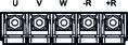
| X2:U | U | Supply system connection |
X2:V | V | ||
X2:W | W | ||
X2:-R | -R | Braking resistor connection | |
X2:+R | +R | ||
| PE | Protective earth connection | |
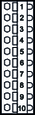
| X60:1 | DO00 | DC link ready |
X60:2 | DO01 | Precharging active | |
X60:3 | DO02 | No function | |
X60:4 | DO03 | Fault | |
X60:5 | GND |
Reference potential | |
X60:6 | GND | ||
X60:7 | MCE | Signal for connecting the line contactor | |
X60:8 | PCE | Signal for connecting the precharging contactor | |
X60:9 | GND |
Reference potential
| |
X60:10 | GND | ||
X60:11 | PCT_GND | ||
X60:12 | PCT | Temperature probe input of the precharging unit | |
| X6:1 | reserv. | Reserved |
X6:2 | |||
X6:3 | |||
X6:4 | |||
X6:5 | |||
X6:6 | |||
| X5:24 V | 24V_in | DC 24 V supply voltage |
X5:GND | GND | Reference potential | |
| DB0/DB00 | reserv. | Reserved |
X10:GND | |||
X10:TF1 | |||
X10:GND | |||
| X20:1 | DI01 | Digital input 1 |
X20:2 | DI02 | Digital input 2 | |
X20:3 | DI03 | Digital input 3 | |
X20:4 | DI04 | Digital input 4 | |
X20:5 | DI05 | Digital input 5 | |
X20:6 | DI06 | Digital input 6 | |
X20:7 | VO24 | DC 24 V voltage output | |
X20:8 | GND | Reference potential | |
X20:9 | reserv.
| Reserved | |
X20:10 | |||
| X22:1 | ||
X22:2 | |||
X22:3 | |||
| X23:1 | ||
X23:2 | |||
X23:3 | |||
X23:4 | |||