Basic design of permanent-magnet brakes
The brakes of the BK.. and BKB.. series are permanent magnet brakes with a DC coil that are released electrically and use the magnetic force of their permanent magnets for deceleration. The following are the key components of the brake system:
- The armature hub [6], which is connected to the motor shaft [7] via a frictional (non‑positive) fit
- The pressure plate [4], which is mounted on the armature hub [6] and is axially movable by means of the return spring [5], and
- The stationary electromagnet, which is attached to the endshield [8]
The electromagnet consists of the magnet body [3] with an integrated brake coil [1] and the permanent magnets [2].
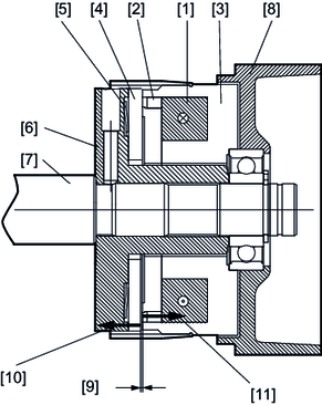

[1] | Brake coil |
[2] | Permanent magnet |
[3] | Magnet body |
[4] | Pressure plate |
[5] | Return spring |
[6] | Armature hub |
[7] | motor shaft |
[8] | Endshield |
[9] | Working air gap |
[10] | Force of the return spring |
[11] | Force of the permanent magnet |
Basic function of the brake
The pressure plate [4] is forced against the magnet body [3] by the permanent magnet force [11] of the permanent magnets [2] when the brake coil [1] is de-energized. The resulting frictional torque is transferred through the return springs [5] and the armature hub [6] to the motor shaft [7], thereby braking the motor shaft [7].
When the appropriate DC voltage is applied to the brake coil [1], an electromagnetic field is generated in the magnet body [3] which cancels out the field effect of the permanent magnets [2] on the pressure plate [4].
The force of the return springs [10] pulls the pressure plate [4] axially to the armature hub [6]. This opens the working air gap [9] and the motor shaft [7] is able to rotate.
The working air gap [9] in permanent magnet brakes results from the production dimensions of the individual parts and the positioning of the brake in the endshield [8]. The working air gap [9] does not require adjustment.
Benefits of permanent magnet brakes
- Compact motor design
- Low intrinsic inertia due to the compact aluminum armature hub
- Free from residual torque, as defined in the operating principle, due to the design with one friction surface
- Armature design without rotational clearance
- Suitable for high cycle rates and short switching cycles
- Simple switching technology without brake control facilitated by the DC 24 V design (e.g. with direct supply from the frequency inverter)
Note that if the braking work Winsp is exceeded, the brake may remain open, and the system can no longer be braked or held.
