Calculation formulas for BK.., BKB.., BP.., BR.., BY.., or BZ.. brakes
No. | Horizontal and vertical (upward) | Vertical (downward) | ||
|---|---|---|---|---|
Static load torque at the motor shaft | Static load torque at the motor shaft | |||
|
|
|
| |
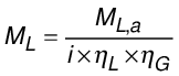
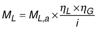
[ML] = Nm | Static load torque at the motor shaft; application and gear unit efficiency are considered "aggravating". | [ML] = Nm | Static load torque at the motor shaft; application and gear unit efficiency are considered "helpful". | |
[ML,a] = Nm | Static load torque value at the output shaft, efficiency not considered |
|
| |
[ηL] = 1 | Efficiency of the application |
|
| |
[ηG] = 1 | Efficiency of the gear unit |
|
| |
[i] = 1 | Gear unit ratio |
|
| |
1.1a
| –
| Checking the braking torque (holding function) | ||
|
| |||
[M4,100 °C] = Nm | Characteristic value of the static braking torque at 100 °C | |||
[fAs] = 1 | Static application factor | |||
1.1b
| –
| Checking the braking torque (emergency stop function) | ||
|
| |||
[M1] = Nm | Characteristic value of the dynamic braking torque | |||
[fAd] = 1 | Dynamic application factor | |||
1.2
| Speed difference at brake application | |||
|
| |||
[nD] = min-1 | Change in motor speed until brake application | |||
[t2] = s | Brake application time; depending on the brake connection type, use t2,I (AC) or t2,II (AC/DC and DC) | |||
[JM] = kgm2 | Motor mass moment of inertia with mount-on components, based on the motor shaft | |||
[JG] = kgm2 | Mass moment of inertia of the gear unit, based on the motor shaft | |||
[JL] = kgm2 | Mass moment of inertia of the application, based on the motor shaft | |||
1.3 | Calculation of emergency-stop speed | Calculation of emergency-stop speed | ||
|
|
|
| |
[nEmergStop] = min-1 | Real emergency stop speed | |||
[nm] = min-1 | Relevant motor speed of the application | |||
1.4a | Checking the maximum emergency-stop speed | |||
|
| |||
[nmax,1] = min-1 | Maximum permitted emergency stop speed depending on the use case | |||
1.4b
| Checking the maximum operating speed | |||
|
| |||
[nMax,0] = min-1 | Maximum permitted operating speed of the brakemotor | |||
1.5 | Checking the no-load switching frequency | |||
|
| |||
[Z] = h-1 | Required cycle switching frequency | |||
[ZB0] = h-1 | Maximum permitted no-load switching frequency of the brake | |||
1.6 | Calculation of maximum occurring braking work | Calculation of maximum occurring braking work | ||
|
| |||
[W1] = J | Maximum occurring braking work during emergency stop | |||
|
|
|
| |
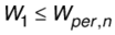
1.7 | Verifying if the braking work is within the maximum permitted braking work | |||
|
| |||
[Wperm,n] = J | Maximum permitted braking work for emergency stop depending on the brake application speed | |||
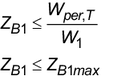
1.8 | For BZ.. brakes: Determining the permitted emergency-stop switching frequency | |||
|
| |||
[ZB1] = h-1 | Permitted emergency-stop frequency (depending on the determined braking work) | |||
[ZB1max] = h-1 | Maximum permitted emergency-stop frequency for the selected load range | |||
[Wper,T] = J×h-1 | Maximum permitted emergency-stop braking work within one hour | |||
1.9 | Calculation of the number of permitted emergency-stop braking operations until brake maintenance | |||
|
| |||
[NB2] = 1 | Number of permitted emergency-stop braking operations until brake maintenance; observe the project planning notes. | |||
[NB2max ] = 1 | Maximum permitted number of emergency-stop braking operations until end of service life | |||
[Winsp] = J | Permitted braking work until brake inspection | |||
[fv] =1 | Wear factor; determination in relation to the used load range for braking work | |||
1.10 | Calculation of the effective torque when braking (gear-unit output side) | Calculation of the effective torque when braking (gear-unit output side) | ||
|
| |||
[Mbrake, output] = Nm | Resulting gear unit load from the braking torque, based on gear unit output shaft |
|
| |
[ηG] = 1 | Gear unit efficiency; for gear units with efficiency ηG < 90%, back-driving efficiency ηG' must be used (see formula 1.11) |
|
| |
[fbrake,output] = 1 | Output design factor |
|
| |
1.11 | Back-driving efficiency for gear units with efficiency ηG < 90% | |||
| ||||
[ηG'] = 1 | Gear unit efficiency (back-driving) | |||
[ηG] = 1 | Gear unit efficiency | |||
1.12 | Checking the emergency stop load (torque) | |||
| ||||
[MaEmerg.Off] = Nm | Maximum permitted emergency stop torque | |||
1.13 | Calculation of the effective gear unit radial force during braking | |||
|
| |||
[FR, brake] = N | Resulting gear unit load due to the radial force generated | |||
[d0] = mm | Diameter of the output shaft transmission element | |||
[fZ] = 1 | Correction factor for the radial force (take into account any additional radial force due to the application, if applicable) | |||
| ||||
1.14 | Verification of the emergency-stop load (radial force) | |||
|
| |||
[FRaEmerg.Off] = N | Maximum permitted emergency-stop radial force for the output shaft; applies when the point of force application is at the center of the shaft end, or at the face end in the case of hollow shafts | |||
1.15 | Calculation of the application’s emergency‑stop speed | |||
|
| |||
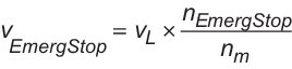
[vEmerg.Stop] = m × s-1 | Real speed at brake application | |||
[vL] = m × s-1 | Relevant speed of the load in the application at the point in time when the emergency stop is requested | |||
1.16 | Calculation of the typical maximum braking time | Calculation of the typical maximum braking time | ||
|
| |||
[tBmax] = s | Maximum typical braking time | |||
[fMmin] = 1 | Braking torque reduction factor | |||
1.17 | Calculation of the typical maximum braking distance | |||
| ||||
[sBmax] = m | Maximum typical braking distance | |||
[tBmax] = s | Maximum typical braking time | |||
1.18 | Calculation of the typical maximum stopping distance | |||
|
| |||
[sAmax] = m | Maximum typical stopping distance | |||
[tSignal] = s | System signal propagation time | |||
1.19 | 1.19a) Calculation of the typical minimum braking time for gear units with ηG ≥ 90% | |||
|
| |||
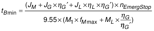
[tBmin] = s | Minimum typical braking time | |||
[fMmax] = 1 | Correction factor for braking torque | |||
1.19b) Calculation of the typical minimum braking time for gear units with ηG < 90% | ||||
|
| |||
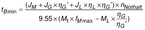
[tBmin] = s | Minimum typical braking time | |||
[fMmax] = 1 | Correction factor for braking torque | |||
1.20 | Calculation of the typical maximum deceleration when braking | |||
|
|
|
| |
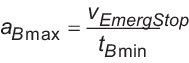
[aBmax] = m × s-2 | Maximum typical deceleration when braking | |||