Transferring the program and testing with simulated logical devices
To test with simulated logical devices, proceed as follows:
- The engineering PC is connected to the engineering interface of the MOVI-C® CONTROLLER via Ethernet. For a point-to-point connection, set "Fixed IP address configured" in the Windows network settings for the Ethernet adapter of the engineering PC and assign an IP address that is in the same address range as the engineering interface of the MOVI-C® CONTROLLER (default IP address:
192.168.20.4). Example: IP address of the engineering PC: 192.168.10.11, subnet mask: 255.255.255.0.
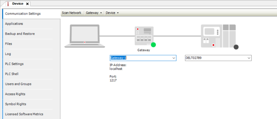
- Open the configuration of the MOVI-C® CONTROLLER.
- Click [Scan Network] in the "Communication" tab.
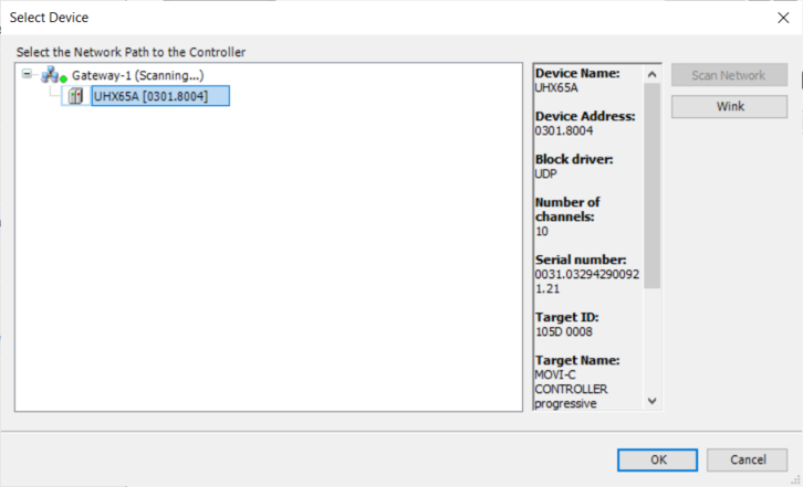
- The "Select Device" dialog box is displayed.
- Select the MOVI-C® CONTROLLER below the corresponding gateway and click [OK].
- The green LED in the "Communication" tab on the MOVI-C® CONTROLLER lights up and the connection to the MOVI-C® CONTROLLER is established.
- Using the edit box below the MOVI-C® CONTROLLER, you can also optionally specify an IP address via which the MOVI-C® CONTROLLER is available in a network.
- Select the [Online] > [Login] menu item.
- The program is loaded onto the MOVI-C® CONTROLLER.
- Select the [Debug] > [Start] menu item.
- The program is started.
- Depending on the application and software module used, carry out the desired tests using the tools Diagnostics and Manual mode.