Arrangement of the modules
The modules can be arranged in one or two rows.
Single-row setup
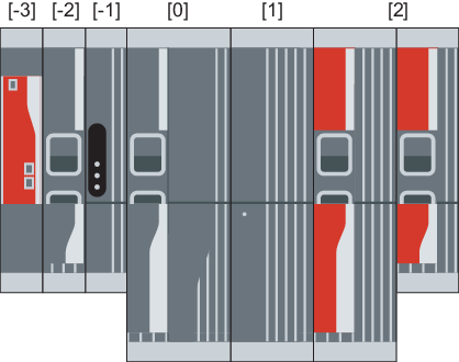
Position | Description |
|---|---|
-3 | UHX45A/MDM90A.. master module |
-2 | MDL91A.. coupling module |
-1 | MDS90A.. switched-mode power supply module |
0 | MDP92A.. power supply module |
1 | MDC92A.. energy modules and MDC90A-0120.. capacitor modules |
2 | Axis modules MDA90A.. and MDD9.A.. |
Observe the following information:
- Always arrange MDC92A.. energy modules and MDC90A-0120.. capacitor modules directly to the right of the MDP92A.. power supply module.
- Always arrange the MDA90A.. and MDD9.A.. axis modules directly to the right of the MDP92A.. power supply module or the MDC92A.. energy module or the MDC90A-0120.. capacitor module, based on the nominal DC link current (descending) from left to right, starting with the axis module with the highest nominal DC link current.
- Arrange the MDS90A.. switched-mode power supply module to the left of the MDP92A.. power supply module.
- Arrange the MDL91A.. coupling module to the left of the MDP92A.. power supply module or the MDS90A.. switched-mode power supply module.
- As an alternative to the specification in the table, you can arrange the UHX45A/MDM90A master module to the far right.
- An MDE90A.. DC/DC converter module can also be combined with an MDP92A.. power supply module. For further information, refer to chapter MDE90A.. DC/DC converter module.
Using an MDC90A-0005.. capacitor module
Observe the following information:
- Note that the order of the devices when using an MDC90A-0005.. is dependent on the MDP92A.. power supply module.
- When using an MDP92A-0100.. power supply module, arrange MDC90A-0005.. capacitor modules directly to the right of the power supply module. Arrange all other modules according to the above regulations regarding the single-row setup.
- When using an MDP92A-0250.. power supply module, arrange MDC90A-0005.. capacitor modules between the axis modules, taking into account the following points:
- Place the axis modules with the highest nominal DC link current between the MDP92A-0250.. power supply module and the MDC90A-0005.. capacitor module.
- The distance between the MDP92A-0250.. power supply module and the MDC90A-0005.. capacitor module must be in the range of 210 mm to 420 mm.
- Axis modules that cannot be placed between the power supply module and the capacitor module due to the maximum distance of 420 mm must be placed to the right of the MDC90A-0005.. capacitor module. Arrange axis modules of this kind from left to right depending on the nominal DC link current (descending), starting with the axis module with the highest nominal DC link current.
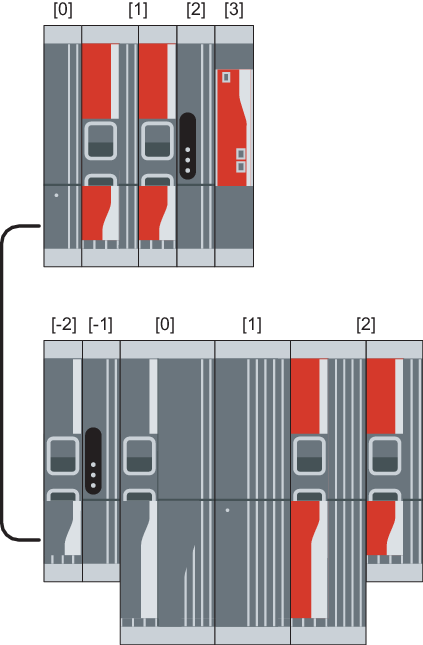
Two-row setup
Position | Description |
|---|---|
0 | MDC90A-0001/0002.. capacitor modules |
1 | Axis modules MDA90A.. and MDD9.A.. |
2 | MDS90A.. switched-mode power supply module |
3 | UHX45A/MDM90A.. master module |
Position | Description |
|---|---|
-2 | MDL91A.. coupling module |
-1 | MDS90A.. switched-mode power supply module |
0 | MDP92A.. power supply module |
1 | MDC92A.. energy modules and MDC90A-0120.. capacitor modules |
2 | Axis modules MDA90A.. and MDD9.A.. |
Observe the following information:
- Always arrange the MDP92A.. power supply module in the main row.
- Arrange the MDS90A.. to the left of the MDP92A.. power supply module.
- Arrange the MDL91A.. coupling module to the left of the MDP92A.. power supply module or the MDS90A.. switched-mode power supply module.
- Always arrange the MDC90A-0001/0002.. capacitor modules to the far left In the auxiliary row.
- Always arrange the MDA90A.. and MDD9.A.. axis modules in the main row directly to the right of the MDP92A.. power supply module or the MDC92A.. energy module or the MDC90A-0120.. capacitor module, based on the nominal DC link current (descending) from left to right, starting with the axis module with the highest nominal DC link current.
- Always arrange the MDA90A.. and MDD9.A.. axis modules in the auxiliary row directly to the right of the MDC90A-0001/0002.. capacitor modules, based on the nominal DC link current (descending) from left to right, starting with the axis module with the highest nominal DC link current.
- Arrange the UHX45A/MDM90A master module to the far right in the auxiliary row.
- Always arrange the MDC90A-0005.. capacitor modules in the main row. Observe the specifications for the single-row setup.
