Installing connections
The following figure shows an example of the procedure for installation of the connections:
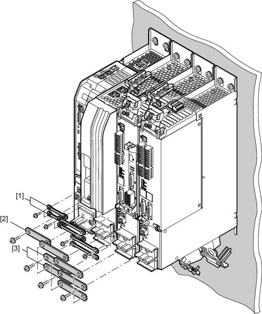
[1] | DC 24 V connection |
[2] | PE connection |
[3] | DC link busbar |
Proceed as follows:
- Install the DC 24 V connection [1] on X5. Tighten the screws with the specified tightening torque.
- Install the PE connection [2]. Tighten the screws with the specified tightening torque.
- Install the DC link busbar [3] on X4. Tighten the screws with the specified tightening torque.
For the specified tightening torques, refer to chapter Permitted terminal tightening torques.
Additional information