Mounting to customer shaft without shaft shoulder
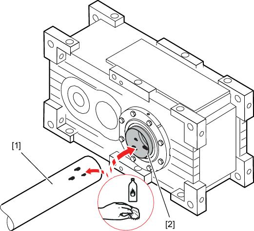
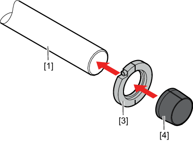
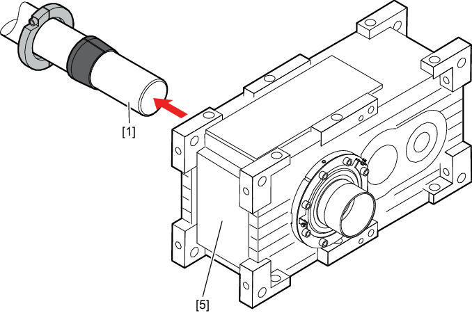
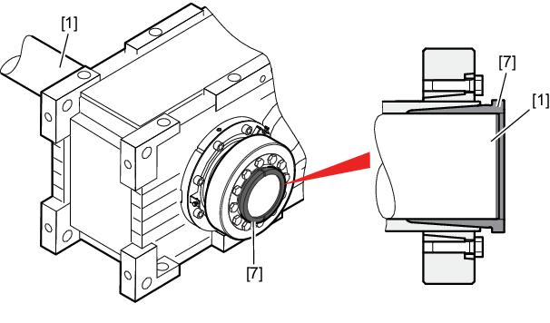
- Clean the customer shaft [1] and the inside of the hollow shaft [2]. Make sure that all grease and oil residues are removed.
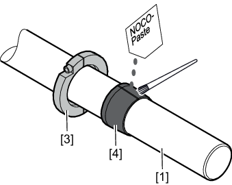
- Mount the stop ring [3] and the bushing [4] on the customer shaft.
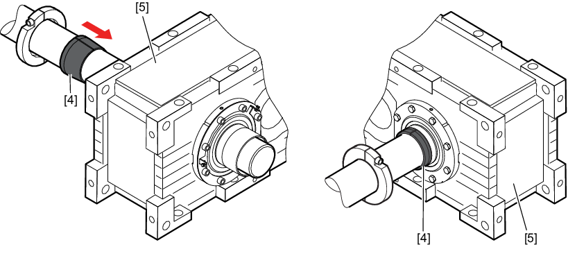
- Apply NOCO-Paste onto the bushing [4] and spread it thoroughly.
- Push the gear unit [5] onto the customer shaft.
- Fasten the gear unit on the mounting surface (do not tighten the screws).
- Slide the bushing [4} into the gear unit [5] up to the stop.
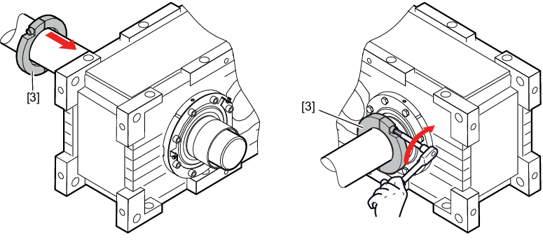
- Secure the bushing with the stop ring [3]. Tighten the stop ring [3] to the bushing with the tightening torque listed in the following table.
Size | Screw | Tightening torque Nm |
|---|---|---|
XT100 | M10 | 79 |
XT110 | M10 | 79 |
XT120 | M10 | 79 |
XT130 | M12 | 116 |
XT140 | M12 | 116 |
XT150 | M16 | 285 |
XT160 | M16 | 285 |
XT170 | M16 | 285 |
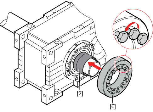
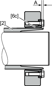
- Make sure that all locking screws are loosened and slide the shrink disk [6] onto the hollow shaft [2].
- Position the inner ring [6c] of the shrink disk to dimension A.
Size | Dimension A in mm |
|---|---|
X100 | 2.5 |
X110 | 4 |
X120 | 7 |
X130 | 7 |
X140 | 3 |
X150 | 5 |
X160 | 5 |
X170 | 10 |
X180 | 10 |
X190 | 10 |
X200 | 3 |
X210 | 3 |
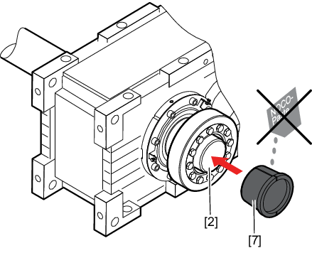
- Slide the counter bushing [7] onto the customer shaft and into the hollow shaft [2].
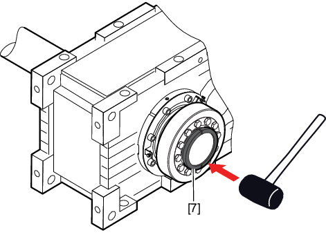
- Tap lightly on the flange of the counter bushing [7] to ensure that the bushing is fitted securely in the hollow shaft.
- Make sure that the customer shaft is seated in the counter bushing.
- Tighten the locking screws [6a] of the shrink disk only manually. Align the taper (outer ring) [6b] parallel to the taper bushing (inner ring) [6c].
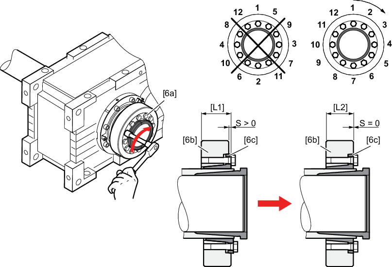
[6a] | Locking screws | [L1] | Delivery state (pre-assembled) |
[6b] | Outer ring | [L2] | Completely assembled (ready for operation) |
[6c] | Inner ring |
INFORMATION

If the taper (outer ring) and the taper bushing (inner ring) cannot be aligned on the face that holds the screws, disassemble the shrink disk again and carefully clean/lubricate it sufficiently.
- Tighten the locking screws clockwise (not in diametrically opposite sequence) by 1/4 revolution. Work around the ring in several stages, evenly tighten the locking screws by a quarter turn each until the taper (outer ring) [6b] and the taper bushing (inner ring) [6c] align on the face that holds the screws.
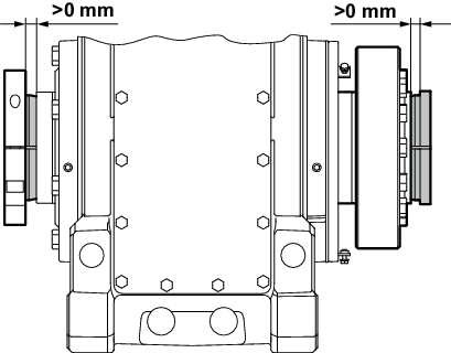
- The remaining gap between stop ring and hollow shaft end, as well as mating bushing and hollow shaft end must be > 0 mm.
- Tighten the retaining screws of the gear unit with the specified tightening torque. Refer to the operating instructions of the gear unit for the tightening torques.