Device structure of switched-mode power supply module with AC and DC supply MDS90A-0054-5E3-X-000
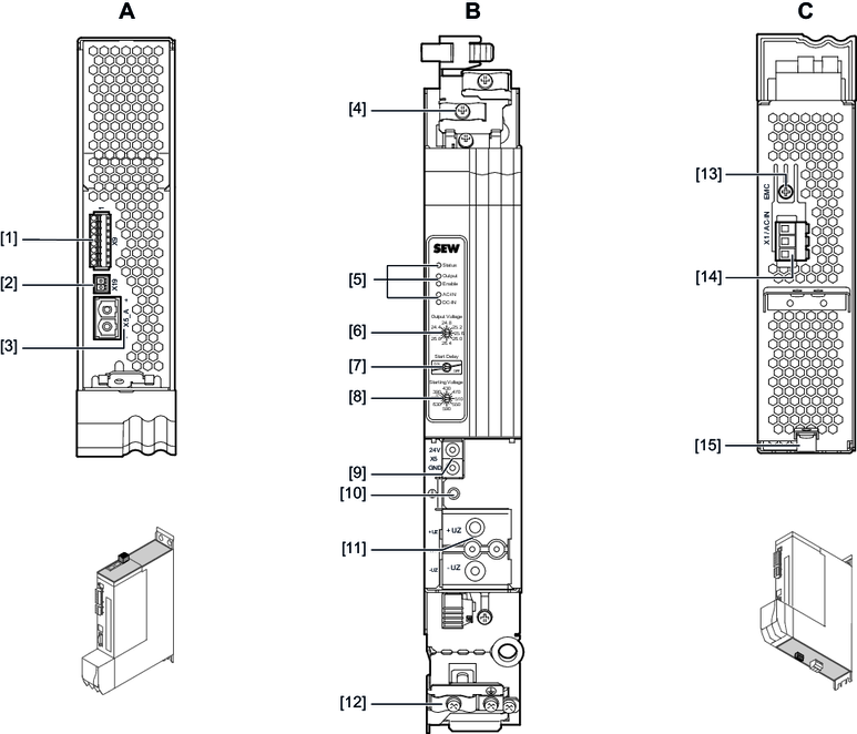
A: View from top | B: View from front | C: View from bottom | |||
[1] | X9: Signal IN/OUT | [4] | Shield plate | [13] | Terminal screw for TN/TT system |
[2] | X19: AC contactor control | [5] | Status LEDs | [14] | X1: Line connection |
[3] | X5_A: Output, DC 24 V supply voltage | [15] | PE connection at housing | ||
|
| [6] | Output voltage selector switch | ||
|
| [7] | Start delay selector switch | ||
|
| [8] | Start voltage selector switch | ||
|
| [9] | X5: 24 V supply voltage connection | ||
|
| [10] | PE connection | ||
|
| [11] | X4: DC link busbar | ||
|
| [12] | Shield plate | ||
