X2016, X2016_1, X2016_2: Inverter output for connecting motors without MOVILINK® DDI
The following table provides information about this connection:
Function | ||
|---|---|---|
Connection of motors without MOVILINK® DDI |
Connection type | ||
|---|---|---|
Han-Modular® 10 B, female, 1 locking latch |
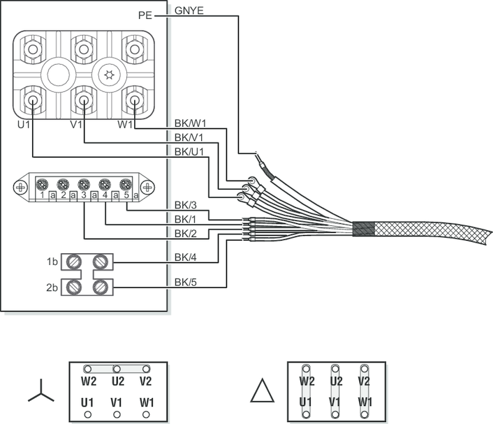
Wiring diagram |
|---|
|
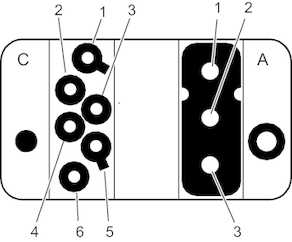
[A] Han® C module, female | ||
|---|---|---|
Contact | Function | |
1 | U | Motor output, phase U |
2 | V | Motor output, phase V |
3 | W | Motor output, phase W |
[C] Han® E protected module, female | ||
|---|---|---|
Contact | Function | |
1 | TF/TH/KTY+ You must observe the type of permitted temperature sensor (TF, TH, or KTY) in chapter "Technical data". | Motor temperature sensor (+) |
2 | 15 | Brake terminal 15 (blue) |
3 | 13 | Brake terminal 13 (red) |
4 | 14 | Brake terminal 14 (white) |
5 | res. | Reserved |
6 | TF/TH/KTY- 1) | Motor temperature sensor (-) |
Articulated frame | ||
|---|---|---|
Contact | Function | |
– | PE | Protective earth connection |
Additional information