28125991, 28125983, 28135342, 28135334, 28170695
The following table shows the core assignment of cables with the following part numbers:
Part numbers | |||||||||
|---|---|---|---|---|---|---|---|---|---|
28125991, 28125983, 28135342, 28135334, 28170695 |
Assembly | |||||||||
|---|---|---|---|---|---|---|---|---|---|
Open cable end, conductor end sleeves, ring cable lugs | Motor connection depending | Assembled plug connector | |||||||
| Without | Three-wire brake AC 110 – 500 V (BE/BZ brake) | Two-wire brake DC 24 V (BK/BP |
| |||||
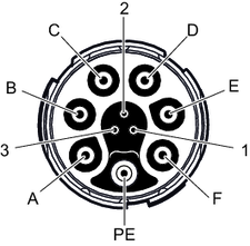
Conductor color/ | Identification | Assembly | Description | Signal | Contact | ||||
Black 1.5 mm2 2.5 mm2 4.0 mm2 | U1 | Ring cable lug | Motor connection, phase U | U | A | ||||
Black 1.5 mm2 2.5 mm2 4.0 mm2 | V2 | Ring cable lug | Motor connection, phase V | V | B | ||||
Black 1.5 mm2 2.5 mm2 4.0 mm2 | W3 | Ring cable lug | Motor connection, phase W | W | C | ||||
Black 1.0 mm2 | 1 | Conductor end sleeve | ReservedReserved conductors must be isolated and fixed in the connection box. | Brake 13 (red) | Brake+ | Brake 13 | D | ||
Black 1.0 mm2 | 2 | Conductor end sleeve | ReservedReserved conductors must be isolated and fixed in the connection box. | Brake 14 (white) | ReservedReserved conductors must be isolated and fixed in the connection box. | Brake 14 | E | ||
Black 1.0 mm2 | 3 | Conductor end sleeve | ReservedReserved conductors must be isolated and fixed in the connection box. | Brake 15 (blue) | Brake- | Brake 15 | F | ||
Green/yellow 1.5 mm2 2.5 mm2 4.0 mm2 | – | Conductor end sleeve | Protective earth connection | PE | PE | ||||
Black 0.34 mm2 | 4 | Conductor end sleeve | Temperature sensor+ connection | Temp+ | 1 | ||||
– | – | – | – | Res. | 2 | ||||
Black 0.34 mm2 | 5 | Conductor end sleeve | Temperature sensor- connection | Temp- | 3 | ||||