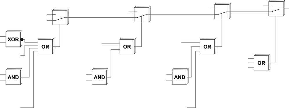
Interrelation between control signals
The control signals have the following significance:
- Controller inhibit
- Rapid stop
- Stop
They are activated via:
- Digital inputs
- Control word processing bus, if P101 control source is set to RS485 or SBus.
- IPOSplus® control word H484
The following table shows the interrelation between control signals. "CW/Stop" is programmed to digital input DIØ1 and cannot be changed. The other control signals are only in effect if a digital input is programmed to this function (→ parameter P60.).
Controller inhibit | Digital input is programmed to | Inverter status | ||
|---|---|---|---|---|
Enable/ Rapid stop | CW/stop (DI01) | CCW/stop | ||
0 | Not relevant
if the digital input is set to controller inhibit and "/Controller
inhibit" = "0" | Not relevant
if the digital input is set to controller inhibit and "/Controller
inhibit" = "0" | Not relevant
if the digital input is set to controller inhibit and "/Controller
inhibit" = "0" | Inhibited |
1 | 0 | Not relevant
if "Enable/rapid stop" = "0" | Not relevant
if "Enable/rapid stop" = "0" | |
1 | 1 | 1 | 0 | CW enabled |
1 | 1 | 0 | 1 | CCW enabled |
As soon as one of the three processing blocks triggers a control command of higher priority (such as "Rapid stop" or "/Controller inhibit"), it will become effective.
The digital inputs will generally remain active even if the inverter is controlled via the process data (P101 control source = RS485 or SBus). Safety-related functions, such as "/Controller inhibit" and "No enable", will be equally processed by the terminal strip and the fieldbus. For control via fieldbus, the frequency inverter must be enabled via a terminal for CW or CCW rotation. The terminal CW or CCW does not determine the direction of rotation. The direction is determined by the sign of the speed setpoint.
All other functions that can be activated via terminals and the control word or IPOSplus® control word will be processed with an OR function.
