Prepare the connection distributor and connect the load cables
The following figure shows the TVS10A connection distributor:
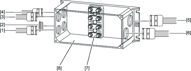
[1] | EMC screw fitting M25 | [5] | EMC screw fitting M32 |
[2] | Screw plug made of metal | [6] | EMC screw fitting M32 |
[3] | EMC screw fitting M25 | [7] | Terminal block in delivery state with four jumper connections in each case |
[4] | EMC screw fitting M25 | [8] | TVS10A connection distributor |
Proceed as follows to connect the load cables:
- To open the TVS10A connection distributor, loosen the four M5 hex head screws on the housing cover.
- First screw in the lower cable glands, and then the upper cable glands and the screw plug in the following sequence: [4], [2], [3], [1].
- Unscrew all the M6 connection screw fittings from the terminal studs.
- Remove the 16 jumper connections.
- Place the jumper connections on the terminal board, as shown in the figure. In the process, note the number of jumper connections.
- Position the three PE conductors included in the accessories pack on the two PE connection points (M6).
- Route the three PE conductors on the internal PE connection [1] of the housing (M5).
- Route the load cable prefabricated with cable lugs through the EMC cable glands.
- Position the cable shields in the EMC screw fittings:
- Position the green/yellow protective earths from the TES load cables on the PE terminal studs.
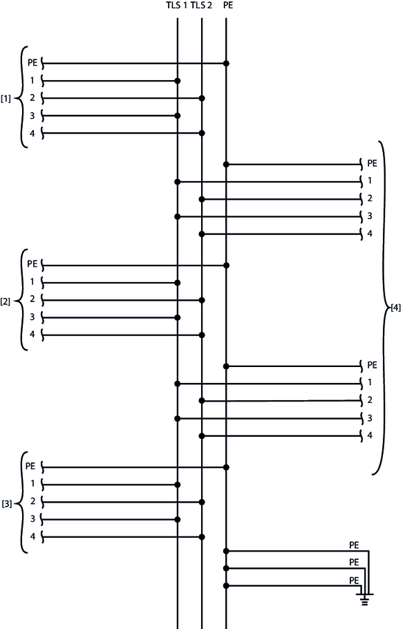
- Place each of the cores 1 + 3 prefabricated with cable lugs on the connections TLS 1.
- Place each of the cores 2 + 4 prefabricated with cable lugs on the connections TLS 2.
- Tighten all of the M6 connection screw fittings inside the housing again (tightening torque: 3.0 Nm).
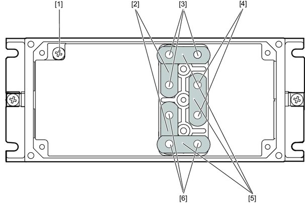
[1] | Internal PE connection | [4] | PE connection points |
[2] | Two jumper connections each | [5] | Four jumper connections each |
[3] | Connections TLS 1 (cores 1 + 3) | [6] | Connections TLS 2 (cores 2 + 4) |
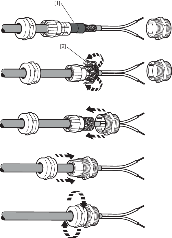
[1] | Remove the heat shrink tubing. Do not damage the braided shield in the process. |
[2] | Fold back the braided shield and shorten it to the correct length. |
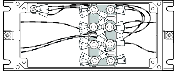
The following figure shows how the individual cores are positioned inside the connection distributor:
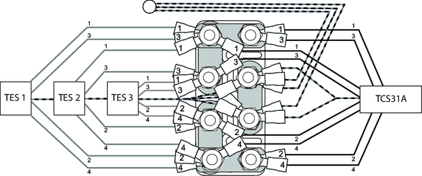
The following figure shows the connection diagram for the connection distributor:
[1] | Load cable TES 1 | [3] | Load cable TES 3 |
[2] | Load cable TES 2 | [4] | Load cable to the TCS31A |
