Single-point synchronization
To increase the transmittable power, only TES31A decentralized supply units of the same type may be connected in parallel.
The parallel connection of TES31A decentralized supply units is only permitted with the "single-point synchronization" device function activated. This device function is only enabled for devices with a nominal power of 14 kW and 16 kW.
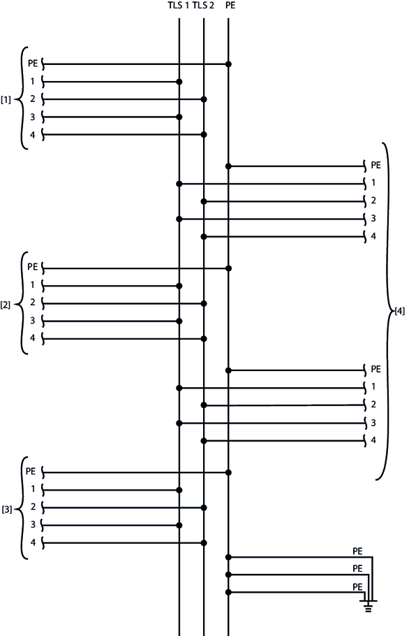
Additional connection cables are required for synchronization. For further information on electrical installation, refer to chapter Cabling for single-point parallel connection.
"Single-point synchronization" device function
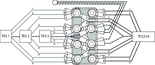
In synchronization mode, one supply unit acts as the SP master. One or two supply units act as SP slaves. The SP master transmits the synchronization signal, the configured setpoint and the enable signal to the SP slaves via the synchronization cable.
In addition to this synchronous enable control function, a closed message chain is required via the digital inputs and outputs.
The following points must be observed:
- There is only one SP master in the synchronization network.
- All synchronization stations (SP master and SP slaves) must have the same frequency and the same load current.
- The frequency mode must be set the same for all synchronization stations (SP master and SP slaves), see chapter "Setpoint selection" in the " MOVITRANS® line TES31A Decentralized Supply Unit" operating instructions.
Fault response with "single-point synchronization"
The "Sync timeout response" parameter is permanently set to "Inhibit output stage" for the SP master and SP slave.
The occurrence of a fault at a synchronization station always leads to output stage inhibit of the complete network via the synchronization cable. When the cause of the fault has been eliminated, the fault is reset as follows:
- via an edge change from "1" to "0" of the "/output stage inhibit" control command at the set control signal source
or alternatively
- via a manual reset in MOVITOOLS® MotionStudio
SP master
If the SP master detects another synchronization signal or faults on the synchronization cable, the SP master executes the fixed "Sync timeout response" fault response and inhibits the output stages of all TES31A supply units involved in the network.
SP slave
In synchronization mode, one or two supply units act as the SP slave. A slave expects the synchronization signal at the synchronization interface and also takes over the setpoint information sent by the SP master. The enable control setting of the preceding TES31A (SP master or SP slave) is taken over and passed on via the interfaces of the digital inputs and outputs. The additional parameter "Sync phase angle" is set to 0°. Modifications are permissible only after consultation with SEW‑EURODRIVE.
If an SP slave receives a faulty synchronization signal, or none at all, the unit executes the fixed fault response and inhibits the output stages of all units involved in the network. In order for the fault response to be triggered, the SP slave must receive a valid synchronization signal and status bit 6 (sync signal active) in the status word must be set to "1".