Connection box and electronics cover (internal) of the MFC1.. design
The following figure shows the connection box and the bottom side of the electronics cover (controller):
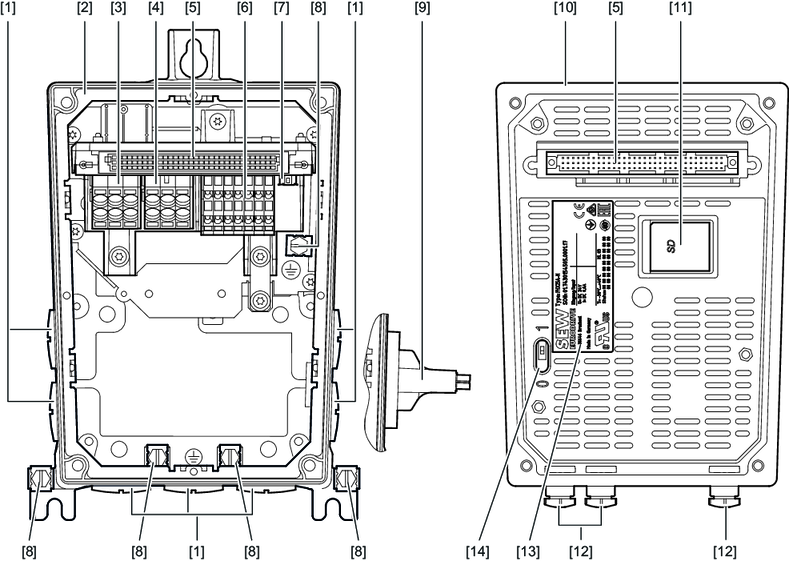
[1] | Cable glands |
[2] | Connection box |
[3] | Connection for supply system |
[4] | Line connection of drive units |
[5] | Connector of connection unit for electronics cover (controller) |
[6] | Electronics terminal strip |
[7] | EtherCAT®/SBusPLUS system bus connection |
[8] | Screws for PE connection |
[9] | Switch disconnector (optional) |
[10] | Electronics cover (controller) |
[11] | SD memory card |
[12] | Plug connectors |
[13] | Nameplate of electronics cover (controller) |
[14] | DIP switch S3 |
