Configuring double devices
A double device features 2 devices that are integrated in the inverter, therefore a B device must be added to the TIA Portal project. A double device allows:
- 8 data bits to be used instead of 4 data bits
- parameters to be accessed via CTT2 services
In the following example, a double device is configured with 8 DI/8 DO data bits and consists of:
- an A device with the S‑7.A.A device profile (CTT3) for drive control
- a B device with the S‑7.A.5 device profile (CTT2) for parameter communication
Proceed as follows:
- The device type and device profile are set via DIP switches on the inverter (see Setting the device type with DIP switches. Note that changing the DIP switch position will also change the device address.
- You have configured a binary device in the TIA Portal project (see Configuring binary devices).
- Open the TIA Portal project that you created when configuring the binary device.
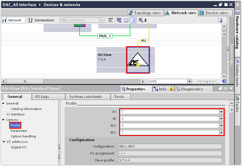
- Change the device profile in the "Profile" group.
- The S‑7.A.A device profile of the A device has been set in this example.
- The S-7.A.A profile (8 DI/8 DO) is designed by AS‑Interface for analog data transmission, which is why the data bits in the PLC are located in the data blocks for analog data. Under "I/O Addresses", the "Digital I/O" group changes to the "Analog I/O" group.
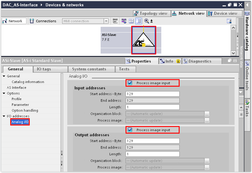
- In the "Analog I/O" group, activate the "Process image for inputs" and "Process image for outputs" check boxes. This means that one I/O byte is available for each of the 8 data bits.
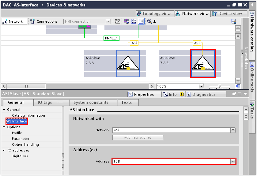
- Open the hardware catalog. Assign a second "AS-i Standard Slave Universal" to the AS‑Interface master.
- Enter the device address of the second device in the "AS‑Interface" group:
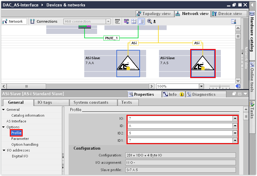
- Enter the device profile of the second device in the "Profile" group.
- In this example, the S‑7.A.5 device profile has been set for the second device (B device).
- Save the TIA Portal project.
- Compile the TIA Portal project and load the project to the PLC.
- To check the settings that have been transferred from the TIA Portal project, switch to the MOVISUITE® project.
- Check the device address, device type, and device profile under [Device properties] > [Communication] > [Fieldbus].
- In this example, the following device parameters have been transferred from the TIA Portal project:
INFORMATION

The acyclic parameter bits of the B device with the S.7.A.5 profile are not supported by SEW‑EURODRIVE. Access to the parameter bits of the A device and to the inverter parameters of the B device by CTT2 services is enabled via a command interface and the instruction ASI_CTRL.
For further information, refer to the documentation of the TIA Portal engineering tool.
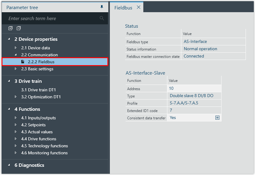
Parameter | Value |
|---|---|
Address | 10 |
Type | Double device 8 DI/8 DO |
Profile | S‑7.A.A/S‑7.A.5 |
A sample project for operating the command interface can be found on the SEW‑EURODRIVE website (www.sew-eurodrive.com). Select [Online Support] > [Data & Documents] > [Software] and search for "TIA sample project MOVI-C®: Parameter access to AS-i- A and B Slave".
