Configuring binary devices
The following example can be reproduced for all devices with 4 DI/4 DO data bits.
The inverter must be added to the TIA Portal project, connected with the PLC, and configured.
Proceed as follows:
- The device type and device profile are set via DIP switches on the inverter (see Setting the device type with DIP switches. Note that changing the DIP switch position will also change the device address.
- The inverter is supplied with line voltage and/or DC 24 V backup voltage.
- The inverter is addressed (see Setting the inverter address).
- MOVISUITE® and TIA Portal are installed on the engineering PC. The engineering PC is connected to the inverter (see Connection of engineering PC – inverter).
- Start the TIA Portal and create a new TIA Portal project.
- Add the PLC and the AS-Interface master to the project.
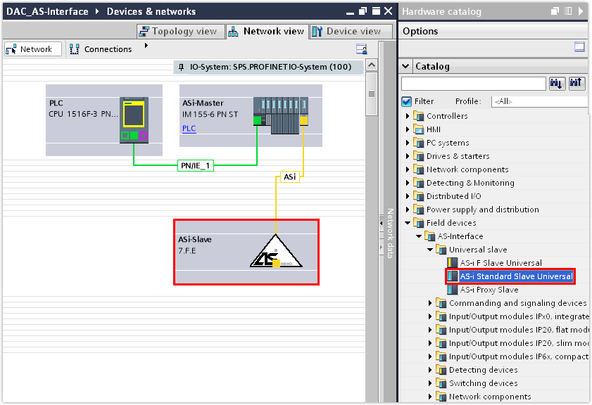
- Open the hardware catalog. Under [Field units] > [Universal modules], select the entry "AS-i Standard Slave Universal" and assign it to the AS-Interface master in the Network view.
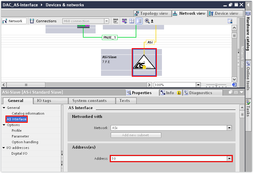
- In the "AS-Interface" group in the inspector window (lower editor section), enter the device address that you have also set in the inverter.
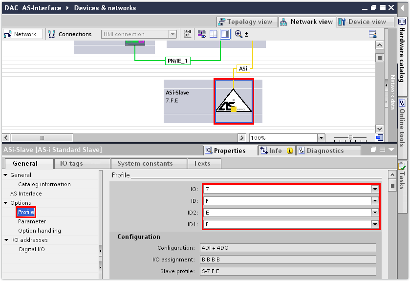
- In the "Profile" group, enter the device profile that you have also set in the inverter.
- The S-7.F.E.F device profile of the binary device has been set in this example.
- Check the setting of the parameter bits in the "Parameters" group.
- The parameter bits are set by default.
- If you are using the MOVIKIT® BinaryTablePositioning Drive software module, the parameter bits are part of a control word and thus have a direct impact on the operating behavior of the drive. In this case, revoke the parameter bits.
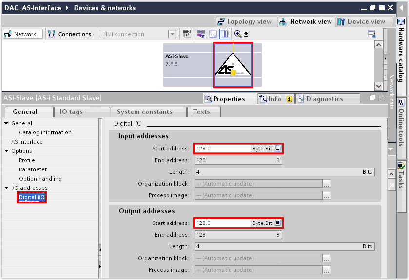
- In the "Digital I/O" group, assign the data bits to the device.
- The S-7.F.E.F profile (4 DI/4 DO) is designed by AS‑Interface for digital data transmission, which is why the data bits in the PLC are located in the data blocks for digital data.
- In this example, the input data bits 128.0 – 128.3 and the output data bits 128.0 – 128.3 are assigned to the device.
- Save the TIA Portal project.
- Compile the TIA Portal project and load the project to the PLC.
- To check the settings that have been transferred from the TIA Portal project, switch to the MOVISUITE® project.
- Check the device address, device type and device profile under [Device properties] > [Communication] > [Fieldbus].
- In this example, the following device parameters have been transferred from the TIA Portal project:

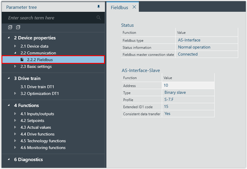
Parameter | Value |
|---|---|
Address | 10 |
Type | Binary devices |
Profile | S‑7.F |
- Check the current state of the input data bits under [Functions] > [Actual values] > [Status word 1]. In the case of a binary device (number of data bits 4 DI/4 DO), only the first 4 status bits are transmitted.
- In this example, the following functions have been assigned to the inputs of the inverter:
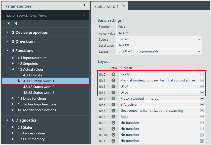
Input data bit | Status bit | Function |
|---|---|---|
E128.0 | Bit 0 | Ready |
E128.1 | Bit 1 | Manual mode |
E128.2 | Bit 2 | DI 01 |
E128.3 | Bit 3 | DI 02 |
- Check the current state of the output data bits under [Functions] > [Setpoints] > [Control word 1]. In the case of a binary device (number of data bits 4 DI/4 DO), only the first 4 control bits are transmitted.
- In this example, the following functions have been assigned to the outputs of the inverter:
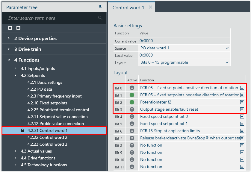
Output data bit | Control bit | Function |
|---|---|---|
A128.0 | Bit 0 | FCB 05 – fixed setpoints, positive direction of rotation |
A128.1 | Bit 1 | FCB 05 – fixed setpoints, negative direction of rotation |
A128.2 | Bit 2 | Potentiometer f2 |
A128.3 | Bit 3 | Output stage enable/fault reset |
