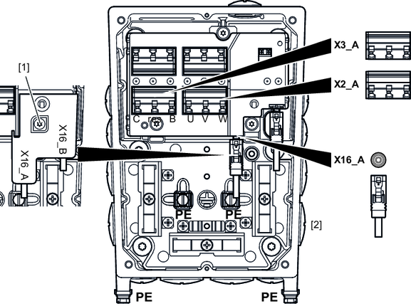
Terminal assignment MGF..2-DSM-C/DI/AZ1Z, MGF..4-DSM-C/DI/AZ1Z and MGF..4-DSM-C/XT/DI/AZ1Z
Observe the wiring instructions in the documentation of the frequency inverter that you use.
Attach units without a plug connector to the terminals as follows:
- De-energize the device. Pay attention to the 5 safety rules in chapter “Carrying out electrical work safely”.
- Secure the output shaft of permanently excited motors against rotation. You thereby avoid an electric shock from the regenerative operation during the rotation of the shaft.
- Loosen the screws of the cover. Remove the cover.
- Route the cables through the cable glands into the connection box.
- Route the cable of the MOVILINK®DDI interface X16_a through the cable gland at position [2].
- For designs with UL, plug in plug connector X16_A as follows:
- Loosen the screw [1]. Remove the cover of the plug connector.
- Plug in the X16_A plug connector.
- Reinstall the cover of the plug connector.
- Connect the unit in accordance with the following terminal assignment.
The following image shows the terminals of MOVIGEAR® MGF..2-DSM‑C/DI/AZ1Z (with MOVILINK® DDI Slave, with AZ1Z encoder):

Terminal | Name | Marking | Function | |
|---|---|---|---|---|
X2_A | U | – | Phase U | |
V | – | Phase V | ||
W | – | Phase W | ||
| PE | – | PE connection | |
X3_A | C | Pink | Reserved | |
Res. | – | Reserved | ||
B | Orange | Reserved | ||
X16_A | DDI | – | MOVILINK® DDI interface | |
The terminal assignment also applies to MGF..4‑DSM-C/DI/AZ1Z and MGF..4‑DSM-C/XT/DI/AZ1Z.

