Brake test
The additional brake test function (operating mode 700) allows you to use the "FCB 21 Brake test" drive function. The drive function tests the function and performance of up to 2 brakes by separately applying an adjustable torque (static test) to the closed brake(s).
The brake test can be adapted ideally to the requirements of the application. The test result "OK" (passed) and "NOK" (failed) and optionally other measured values are available as feedback for each brake.
An application-specific load torque must be taken into account when specifying the torque. The user can specify a value. As an alternative, the FCB 21 can determine the current load situation itself. This simplifies startup and offers more flexibility in the application.
FCB 21 works with drive train 1 (DT1). An encoder feedback (motor encoder or external encoder) that matches the required VFCPLUS, CFC or servo control mode is required.
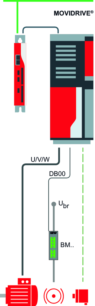
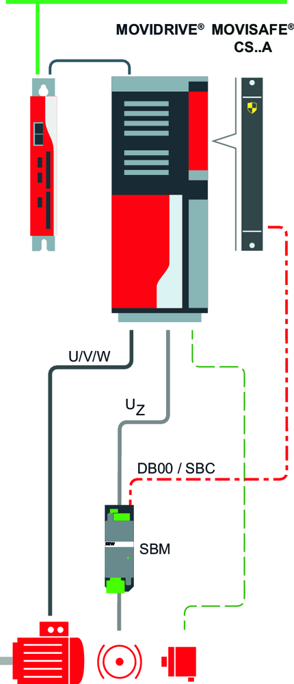
When executing the FCB 21 brake test for testing a brake, the brake control is integrated via DB 0/DB 00.
System example 1 |
| System example 2 |
|
Brake control with | Safe brake control with | ||
|
|
|
|
When executing the FCB 21 brake test to test two brakes, the two brakes will be tested separately. This requires additional wiring for separate control of the two brakes.
System example 3 |
| System example 4 |
|
Brake control with | Safe brake control with | ||
|
|
|
|
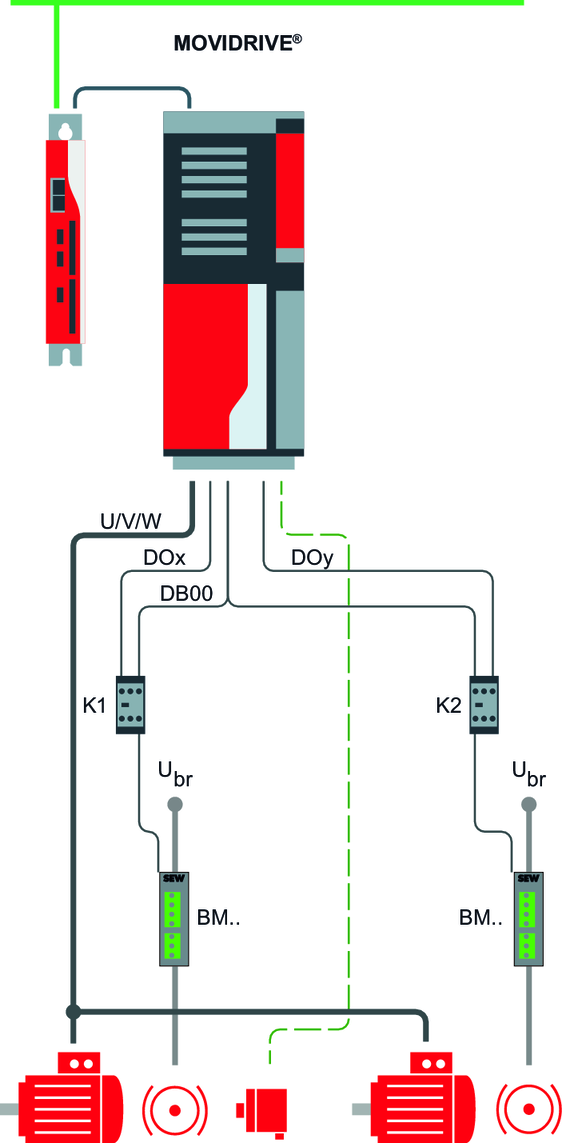
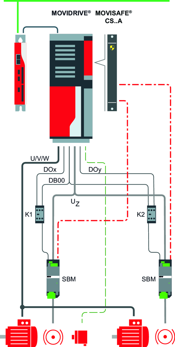
System examples 3 and 4 show the additional relays K1 and K2 required during brake control DB 0/DB 00. When FCB 21 brake test is active, the two relays K1 and K2 are switched alternately by FCB 21. This applies the brake to be tested while the other brake remains released. The wiring of the brake control DB 0/DB 00 must be routed to relays K1 and K2 via NC contacts (low-active).
Relays K1 and K2 are controlled by FCB 21 via control signals. These can be freely assigned, e.g. to PI data, digital outputs or I/O extension of the inverter. SEW‑EURODRIVE recommends using the digital outputs of the inverter or the I/O extension.
Assign the following signals of FCB 21 to the required digital outputs:
- For brake 1 (DOx in the example): "FCB 21 Brake test – apply brake 1"
- For brake 2 (DOY in the example): "FCB 21 Brake test – apply brake 2"
For more information on configuring digital inputs/outputs, refer to chapter Digital inputs/outputs.
