Creating an IEC project in "Startup" mode with simulated axes
Creating an IEC project in "Startup" mode with simulated axes allows for preparing an application at the office, for example.
The example described in the following is a MOVI‑C® CONTROLLER that can be used to scan the axes. The axes are not physically present and connected or are only partly physically present and connected. In this case you can create an IEC project from a combination of physically present axes and simulated axes. The following figure illustrates the situation described above:

Perform the following steps to start up this constellation in MOVISUITE® and to prepare the creation of the IEC project:
- The physically present devices are cabled as shown in the figure.
- Connect your engineering PC with the MOVI‑C® CONTROLLER.
- Create a new MOVISUITE® project choosing the option "From network scan". See chapter Creating the MOVISUITE® project.
- Perform the startup procedure for both drives. See chapter Starting up the drives.
- Perform the startup procedure for the MOVI‑C® CONTROLLER. See chapter Starting up the MOVI-C® CONTROLLER.
- Switch to "Planning" mode.
- Select and copy the axes "DoubleAxis1", "DoubleAxis2" and "SingleAxis1", and insert them under the MOVI‑C® CONTROLLER.
- By copying the double axes and the single axis, their parameter setting is adopted as well. This means the axes need not be configured anymore.
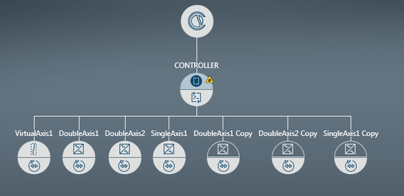
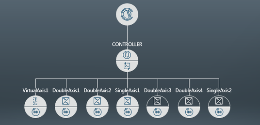
- Rename the added axes in such a way that your MOVISUITE® project looks as follows in the function view:
- The axes to be simulated are not available in the network and are therefore not connected with a device in the network view. The upper half of axes that are not connected is indicated as transparent.
- Open the configuration of an axis that is to be simulated.
- Under "MultiMotion", open the submenu "Basic settings".
- In the "General" section, set the value for "Activate simulation" to "Yes".
- Repeat these 3 previous steps for all axes that are to be simulated.
- Generate the IEC project. See chapter Generating an IEC project.
- Automatic code generation will generate the configuration data.
- The axis data sets of the physically present axes are synchronized with the devices.
- All data sets and the configuration data are then transferred to the memory card of the MOVI‑C® CONTROLLER.
- The IEC project is updated.
INFORMATION

If you want to use another drive train, first add the axes from the catalog and then configure them as described in chapter Starting up the drives.
- Now you can use this IEC project to prepare programming and to perform real or simulated tests with these axes.
