Configuring devices in the IEC Editor
The devices that are subordinate to the MOVI‑C® CONTROLLER must first be manually configured in the IEC editor. Only then they are detected during a network scan and can be added to the MOVISUITE® project.
INFORMATION

Number and arrangement of the devices and modules in the IEC editor project must match the real hardware topology.
Proceed as follows:
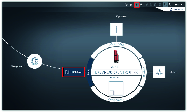
- Switch to circle navigation and start the IEC editor.
- A message on the used compiler version is displayed.
- Keep the current compiler version. Click the [Cancel] button in the message window.
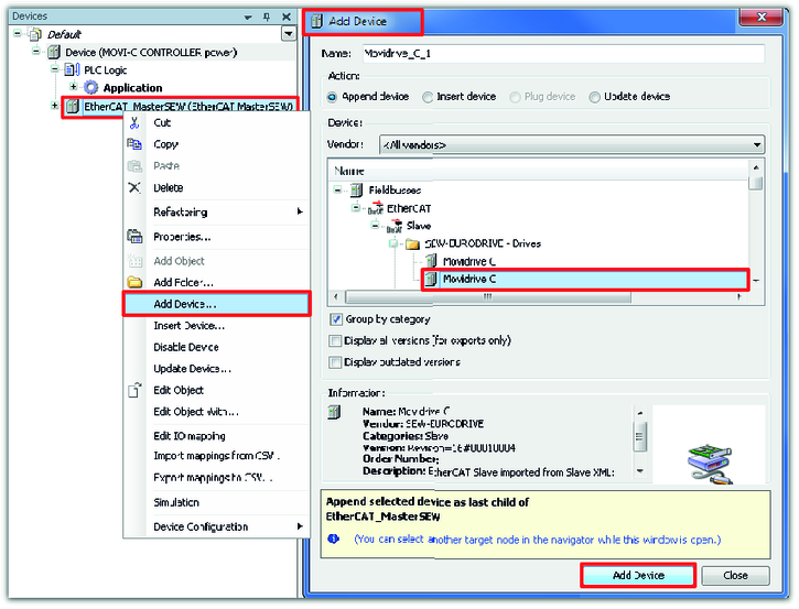
- A lower-level device must be added below the EtherCAT®/SBusPLUS master in the device tree. Open the context menu of the master by right-clicking and select the required device from the device list in the "Add device" window.
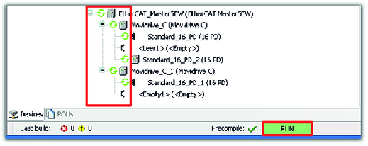
- In this example, the MOVIDRIVE® modular application inverters are lower-level devices.
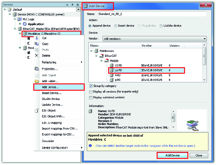
- The MDD90A double-axis module is displayed in the IEC editor project with additional process data. Open the context menu of the respective application inverter by right-clicking and select the required number of process data words from the device list in the "Add device" window.
- In this example, each module communicates with the MOVI‑C® CONTROLLER with 16 process data words.
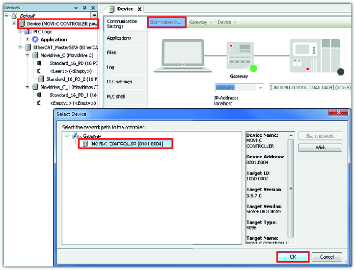
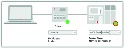
- To establish a connection from the IEC editor project to the MOVI‑C® CONTROLLER, double-click on the MOVI‑C® CONTROLLER (device) in the device tree and scan the network. Add the found device.
- If the connection is established, the LED of the MOVI‑C® CONTROLLER lights up green.
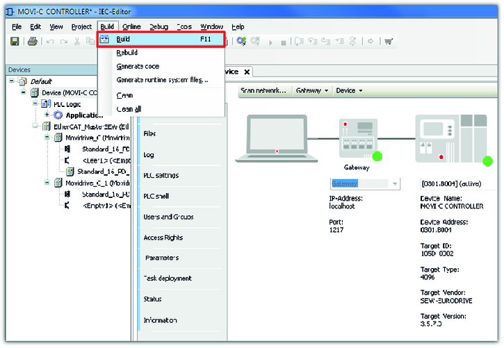
- Build the IEC program in the machine code of the MOVI‑C® CONTROLLER.
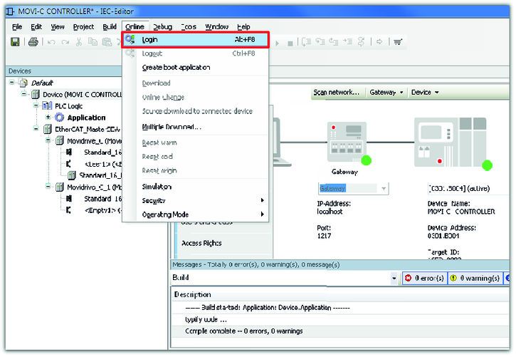
- If the build of the IEC program was successful, the program can be transferred to the MOVI‑C® CONTROLLER. For this purpose, log on to the network.
- A message is displayed that the IEC program (application) from the IEC editor program has been created and loaded to the MOVI‑C® CONTROLLER.
- Confirm this message.
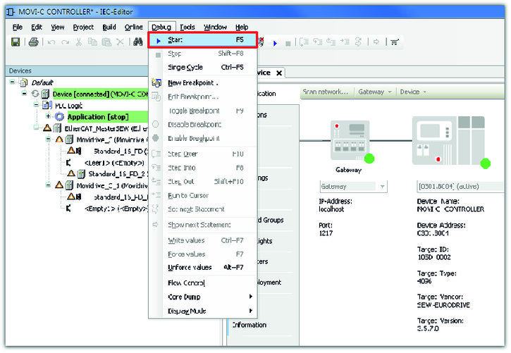
- Start the IEC program.
- The MOVI‑C® CONTROLLER starts. The message "RUN" is displayed in the status bar of the IEC editor.
- If communication with the lower-level devices is established, the devices are marked with a green circle in the device tree.
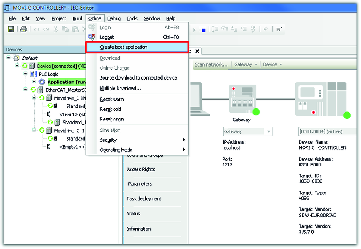
- Create a boot project. This way, the IEC editor project is stored on the CFast memory card of the MOVI‑C® CONTROLLER and is still available after a restart of the MOVI‑C® CONTROLLER.
- Close the IEC editor and confirm the message.