Connection of MWA21A option
For information about installing the MWA21A option, refer to chapter Installation of MWA21A option.
The following figure shows how to connect the MWA21A option:
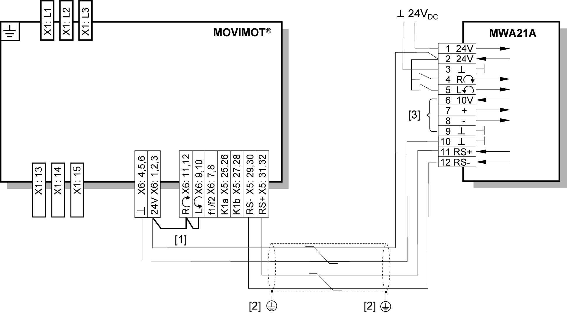
[1] | Note the enabled direction of rotation. |
[2] | EMC metal cable gland |
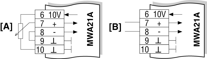
[3] | Potentiometer using the 10 V reference voltage [A] |
|