MCR91A.. regenerative power supply
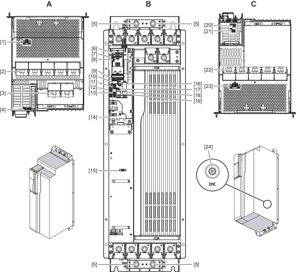
A | View from top |
[1] | X5: 24 V supply voltage |
[2] | X1: Connection to the precharging unit and to +UDCL, -UDCL: DC link connection on rectifier side |
[3] | +UDCL*, -UDCL*: DC link connection capacitor side |
[4] | X6: No function |
|
|
B | View from front |
[5] | 4 × housing PE connection |
[6] | X32: Diagnostic interface |
[7] | Product label with QR code |
[8] | S1/S2: EtherCAT® ID switch |
[9] | Status LEDs |
[10] | Capacitor module |
[11] | X23: Reserved |
[12] | X20: Digital inputs |
[13] | X22: Reserved |
[14] | Signal and control cable shield plate |
[15] | Shield plate |
[16] | X60: Digital outputs / connection to the precharging unit |
[17] | S4: No function |
[18] | X30/X41 OUT: Fieldbus |
[19] | X30/X40 IN: Fieldbus |
|
|
C | View from below |
[20] | X18: No function |
[21] | X16: No function |
[22] | X2: Connection for supply system and braking resistor |
[23] | X10: No function |
[24] | EMV contact screw on the right side of the device |
