Tower sway
- Specify the "Distance between lifting and traveling trolley" (at this lifting height, oscillation should be suppressed) by configuring the "Source of distance between lifting and traveling trolley".
- Configuration value: Use the value specified manually in the "Distance between lifting and traveling trolley" settings field in the "Basic settings" section.
- Configured axis: Use the position of a configured axis such as the lifting axis as a value. This way, sway suppression is always adapted to the lifting height or to the distance between the lifting trolley and the traveling trolley. To do so, select and configure the axis using the displayed settings fields. A "Lifting position offset" can be used here to calculate the compensation if the value from the axis does not match the actual distance between lifting and traveling trolley. You can also select the user unit of the lifting axis or enter a user-defined conversion factor for the user unit in meters. Note that when using an axis for the lifting height, this axis must first be enabled briefly during startup so that the current lifting height can be used as the basis for calculating the anti-sway control in the travel axis.
- Configure the mechanical parameters of the application in the "Basic settings" section. The following figure illustrates the parameters available for this application type. For detailed descriptions of the parameters, refer to chapter Anti-sway control. If you do not already know the "Spring stiffness between tower and traveling trolley" and the "Damping ratio between tower and traveling trolley", e.g. from mechanical simulations, you can apply the suggested values calculated from the previously configured mechanical parameters here. If the suggested values do not lead to a satisfactory result, select the "From measurement" option for Support for parameter determination and determine the parameters specifically for your application as described in Determination of parameters for spring stiffness.
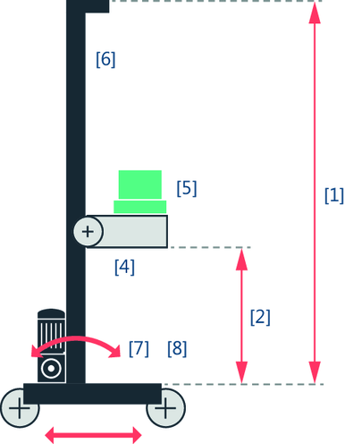
[1] | Height of the tower |
[2] | Distance between lifting and traveling trolley |
[4] | Mass of the lifting trolley |
[5] | Mass of the payload |
[6] | Mass of the tower |
[7] | Spring stiffness between tower and traveling trolley INFORMATION: To determine this parameter, see chapter Determination of parameters for spring stiffness. |
[8] | Damping ratio between tower and traveling trolley INFORMATION: To determine this parameter, see chapter Determination of parameters for spring stiffness. |
- Define the time window by configuring the "Ramp time tension build-up" and the "Jerk time tension build-up" in the "Time window" section. These parameters describe the respective duration of the mechanical tension build-up. For longer times, more time is used for sway suppression, thereby reducing the dynamics of the correction signal. The positioning process is extended by these times. However, the jerk time of the travel axis can be reduced at the same time. A value is suggested for both parameters that you can adopt and adjust if necessary. The "Cycle time of the HighPrio task for limit value calculation" is also displayed in this section. The displayed value is taken from the "Controller setpoint cycle" parameter of the lower-level member.
